
GEWU DOCUMENTATION
GW-CO-GARY Gray Code to RS485 Converter Guide
Converts Gray-code position data to RS485 for legacy device connectivity. Learn the product capabilities, first-use steps and support options.
What should I know about GW-CO-GARY Gray Code to RS485 Converter Guide?
Converts Gray-code position data to RS485 for legacy device connectivity. Learn the product capabilities, first-use steps and support options.
1. Function Description
This module converts gray‑code signals to RS‑485 Modbus protocol. It supports up to 15‑bit gray‑code input. Gray‑code signals from encoders, displacement sensors and other devices can be converted into standard Modbus data for communication with host computers or RTUs over the RS485 bus.
2. Technical Specifications
Basic Parameters
| Item | Parameter | Remarks |
|---|---|---|
| Product Model | GW‑CO‑GRAY | |
| Supply Voltage | 5~28 VDC | |
| Operating Current | <10 mA | |
| Ingress Protection | IP30 (Non‑waterproof; install inside control cabinet) | |
| Operating Temperature | -40~85 ℃ | |
| Operating Humidity | 0~95 % RH (non‑condensing) | |
| Overall Dimension | 82 × 66 × 18 mm | |
| Mounting Method | DIN‑rail mounting |
Measurement Parameters
| Item | Parameter | Remarks |
|---|---|---|
| Measuring Range | Max. 15 bits |
Communication Parameters
| Item | Parameter | Remarks |
|---|---|---|
| Physical Interface | RS485 | Baud rate 9600, 8N1 |
| Communication Protocol | MODBUS | Custom non‑standard protocols supported |
| Physical Interface | USB‑TYPEC | USB‑TTL |
| Physical Interface | 15‑bit gray‑code input |
LED Indicators
| Indicator | Description |
|---|---|
| RUN | Run indicator (flashes during normal communication) |
| POWER | Power indicator (steady‑on for normal power supply) |
3. Terminal Definition
Top Terminals
| No. | Label | Description |
|---|---|---|
| 1 | VCC | Module power supply, 5‑28 VDC |
| 2 | GND | Power ground |
| 3 | 485A | RS485+ |
| 4 | 485B | RS485‑ |
Bottom Terminals
| No. | Label | Description |
|---|---|---|
| 1 | DIN01 | Gray‑code input Bit 1 |
| 2 | DIN02 | Gray‑code input Bit 2 |
| 3 | DIN03 | Gray‑code input Bit 3 |
| 4 | DIN04 | Gray‑code input Bit 4 |
| 5 | DIN05 | Gray‑code input Bit 5 |
| 6 | DIN06 | Gray‑code input Bit 6 |
| 7 | DIN07 | Gray‑code input Bit 7 |
| 8 | DIN08 | Gray‑code input Bit 8 |
| 9 | DIN09 | Gray‑code input Bit 9 |
| 10 | DIN10 | Gray‑code input Bit 10 |
| 11 | DIN11 | Gray‑code input Bit 11 |
| 12 | DIN12 | Gray‑code input Bit 12 |
| 13 | DIN13 | Gray‑code input Bit 13 |
| 14 | DIN14 | Gray‑code input Bit 14 |
| 15 | DIN15 | Gray‑code input Bit 15 |
| 16 | COM | Common terminal |
4. Power Supply
The module accepts 5‑28 VDC power input. It supports common battery sources such as 2‑6 series lithium‑ion battery packs and 1‑2 series storage batteries. The module does not enter sleep mode after power‑on. It is of low‑power design with current consumption below 10 mA under full‑speed operation. For power‑critical systems, connect VCC to a controllable power output of the main controller to reduce overall power consumption.
5. Protocol Description
Factory defaults: baud rate 9600, 8 data bits, 1 stop bit, no parity, Modbus‑RTU protocol. Custom non‑standard protocols are available for drop‑in replacement without modifying main‑controller logic.
5.1 Device Address
Default device address is 1, configurable via commands. If the address is forgotten, read data using address 0 to detect the actual device address.
When address 0 is used, ensure only one device is connected on the bus.
| Parameter | Register Address | Data Type | Function Code | Description | Default Value |
|---|---|---|---|---|---|
| Converted Gray‑Code Data | 0x0000 | uint16 (Read‑Only) | 0x03 | Converted value | 0 |
| Raw Gray‑Code Data | 0x0001 | uint16 (Read‑Only) | 0x03 | Raw input value | 0 |
| Correction Factor K | 0x0002 | float (Read‑Write) | 0x03/0x16 | 1 | |
| Correction Offset B | 0x0004 | float (Read‑Write) | 0x03/0x16 | 0 | |
| Valid Bit Count | 0x0006 | uint16 (Read‑Write) | 0x03/0x06 | Max. 15 bits | 12 |
| Device Address | 0x03E8 | uint16 (Read‑Write) | 0x03/0x06 | 1 | |
| Restore Factory Defaults | 0x03E9 | uint16 (Read‑Write) | 0x03/0x06 | 0 | |
| Firmware Version | 0x03A0 | uint16 (Read‑Only) | 0x03 |
5.2 Communication Examples
Example note: Read converted data (example return value 600 mm)
Read Converted Gray‑Code Data
| Transmit | 01 03 00 00 00 01 84 0A |
|---|---|
| Response | 01 03 02 02 58 B8 DE |
Modify Device Address (from 01 to 02)
| Transmit | 01 06 01 01 00 02 58 37 |
|---|---|
| Response | 01 06 01 01 00 02 58 37 |
6. Installation and Configuration
6.1 Hardware Connection
- Gray‑code input: Connect encoder pins DIN01‑DIN0N sequentially to module terminals DIN01‑DIN0N (observe signal‑level matching). Connect the COM common terminal.
- RS485 bus: Connect module 485A / 485B to bus A / B terminals. For multi‑device networks, ensure unique slave addresses.
- Power supply: Apply DC 5‑28 V, observe correct polarity.
6.2 Software Configuration
You may view data and configure parameters with any serial‑port debugging tool using commands given in preceding chapters. Operation via visual tool Gewu Online Tool is recommended; no deep knowledge of underlying Modbus frame format is required.
- Select official template: GW‑CO‑GRAY Gray‑Code‑to‑RS485 Module.

- Serial‑port parameters: 9600‑8‑N‑1.
- Click Connect Serial Port and select the serial‑port adapter connected to your computer.

- Click Start Polling.

- To write parameters, navigate to the corresponding register, enter the value and click Confirm Write.

7. Dimensions
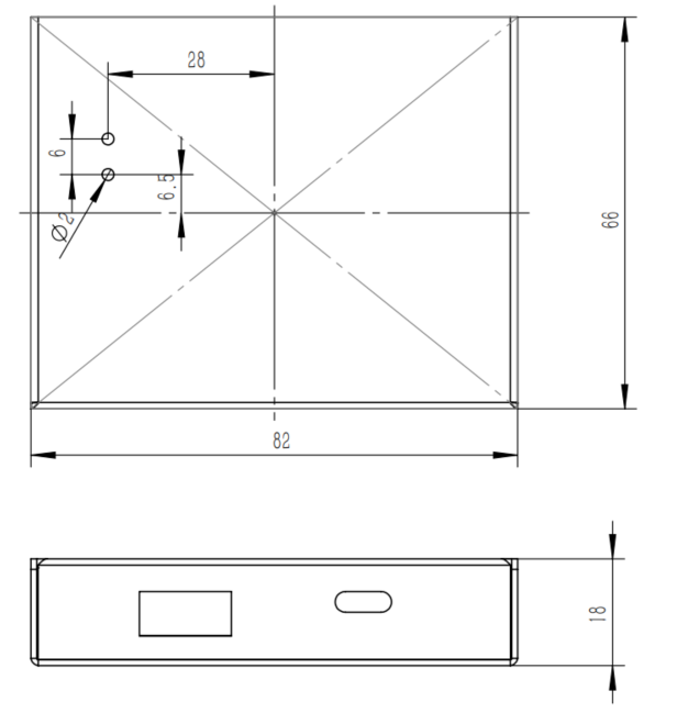
Overall dimension: 82 × 66 × 18 mm
8. Precautions
Wiring Requirements
‑ Keep gray‑code signal wires and RS485 bus cables at least 30 cm away from high‑voltage power lines. ‑ Use shielded twisted‑pair cable for RS485 bus; ground the shield at one end only.
Communication Conflicts
‑ Do not assign duplicate slave addresses on one bus segment. ‑ For half‑duplex communication, the master shall wait for slave response before sending the next command.
Gray‑Code Compatibility
‑ Confirm the encoder outputs binary gray code. ‑ Leave higher‑order inputs DIN13~DIN15 unconnected if unused (e.g. for 12‑bit gray‑code devices).
Official website: www.gewuiot.com