
GEWU DOCUMENTATION
GW-GG-A Standard Gateway RTU Guide
Cost-efficient gateway supporting up to 32 sensors and common water-industry protocols. Learn the product capabilities, first-use steps and support options.
What should I know about GW-GG-A Standard Gateway RTU Guide?
Cost-efficient gateway supporting up to 32 sensors and common water-industry protocols. Learn the product capabilities, first-use steps and support options.
| Version | Description | Date |
|---|---|---|
| V1.0 | March 15, 2023 |
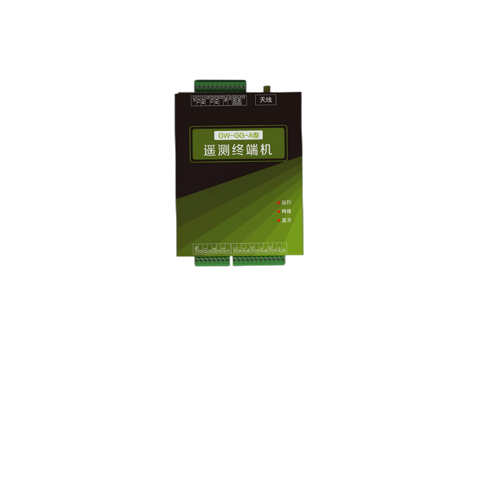
1. Product Overview
Designed for general‑purpose data‑acquisition scenarios, this product connects multiple standard RS485‑Modbus sensors. It features flexible and configurable data collection & reporting logic, practical functions including low‑power‑consumption management, sensor power‑supply control and on‑board storage, and facilitates building various types of data‑monitoring stations.
The device supports 7‑28 V wide‑voltage power supply and is compatible with various DC power sources, storage batteries and primary batteries.
It delivers ultra‑low power consumption with whole‑device sleep current less than 0.1 mA. It can complete server connection and data reporting within 5 s, which greatly reduces average power consumption.
Product Features: ‑ All‑metal housing for enhanced equipment reliability ‑ Built‑in Bluetooth: supports wireless wake‑up at any time via mobile‑phone APP to improve operation‑and‑maintenance efficiency ‑ 4G nationwide cellular network ‑ Multi‑channel support: each channel supports independent reporting protocols and station addresses ‑ OTA remote firmware upgrade
2. System Parameters
Basic Parameters
| Item | Parameter |
|---|---|
| Product Model | GW‑GG‑A |
| Supply Voltage | 7‑28 VDC |
| Sleep Current | <0.1 mA |
| Sensor Power Supply | 1‑channel constant‑voltage VCC output 3‑channel controlled VCC output with configurable power‑on delay |
| Hardware Interfaces | 1 × RS485 sensor interface (multiplexing supported) 1 × TTL serial port 1 × RS232 interface 3 × DI digital‑input channels |
| Acquisition Functions | Optional on‑board temperature‑humidity measurement Compatible with tipping‑bucket rain gauges Supports reading parameters from up to 32 RS485‑Modbus sensors Software‑configurable baud rate, device address, register address and data format for each sensor Secondary correction of raw data Supports docking with non‑standard RS485 peripheral protocols |
| Network Functions | Built‑in 4G nationwide cellular communication module Built‑in BLE Bluetooth module Supports Alibaba Cloud IoT platform access (custom‑protocol development available for other platforms) Supports SL651 hydrological protocol, SZY206 water‑resource protocol, etc. Supports resume‑transmission after power outage Supports remote firmware upgrade |
| Other Functions | Expandable high‑precision positioning, LED large‑screen display, touch‑screen display and other non‑standard functions |
3. Installation Instructions
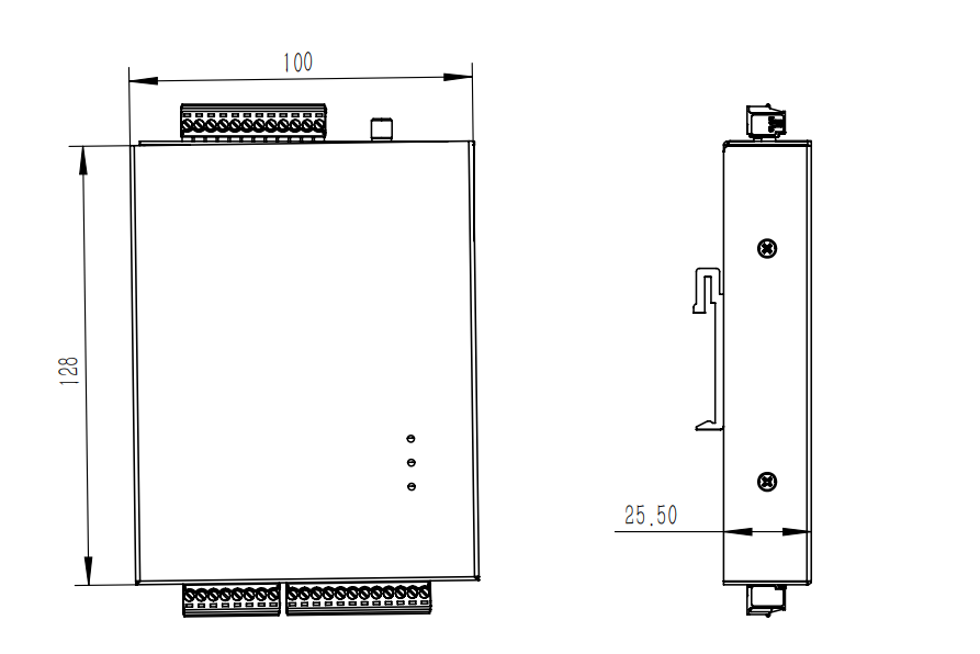
Mounting Method: Standard 35 mm DIN‑rail mounting.
The gateway uses 3.512 and 3.58 plug‑in terminal blocks. Terminals are detachable for convenient wiring in narrow spaces.
Terminal Definition Table
| No. | Label | Function Definition | Remarks |
|---|---|---|---|
| 1 | VI | Power Input | 7‑28 VDC; built‑in reverse‑polarity and surge protection |
| 2 | G | Ground | |
| 3 | D1 | Digital Input 1 | For tipping‑bucket rain gauges, push‑buttons and other devices |
| 4 | G | Ground | |
| 5 | D2 | Digital Input 2 | For tipping‑bucket rain gauges, push‑buttons and other devices |
| 6 | G | Ground | |
| 7 | D3 | Digital Input 3 | For tipping‑bucket rain gauges, push‑buttons and other devices |
| 8 | G | Ground | |
| 9 | VC | Power Output | Same as input voltage |
| 10 | G | Ground | |
| 11 | A+ | RS485 A+ | |
| 12 | B‑ | RS485 B‑ | |
| 13 | VO1 | Controlled‑voltage Output | For low‑power sensors; power‑on delay configurable |
| 14 | G | Ground | |
| 15 | A+ | RS485 A+ | |
| 16 | B‑ | RS485 B‑ | |
| 17 | VO1 | Controlled‑voltage Output | For low‑power sensors; power‑on delay configurable |
| 18 | G | Ground | |
| 19 | A+ | RS485 A+ | |
| 20 | B‑ | RS485 B‑ | |
| 21 | VC | Power Output | Same as input voltage |
| 22 | TX1 | RS232 TXD | |
| 23 | RX1 | RS232 RXD | |
| 24 | G | Ground | |
| 25 | TX2 | TTL TXD | |
| 26 | RX2 | TTL RXD | |
| 27 | G | Ground | |
| 28 | VC | Power Output | Same as input voltage |
| 29 | VO2 | Controlled‑voltage Output | For low‑power sensors; power‑on delay configurable |
| 30 | G | Ground | |
| 31 | VO3 | Controlled‑voltage Output | For low‑power sensors; power‑on delay configurable |
| 32 | G | Ground |
Classification of Field‑deployed Sensors
- Category 1: Fast‑start Numeric Sensors Examples include temperature, pressure and liquid‑level sensors. Connect sensor power supply to VO controlled‑voltage pins, and set the sensor power‑on delay longer than the sensor startup time.
- Category 2: Non‑power‑off Sensors Examples include flow meters and rain gauges, which require continuous power supply for constant data recording. Use external constant‑voltage power supply or connect to VC terminals of the device to prevent data loss caused by power failure.
- Category 3: Long Warm‑up Time Sensors without Continuous Recording Examples include electrochemical CO₂ sensors and certain water‑quality sensors that take several minutes for readings to stabilize after power‑on. ‑ Short acquisition interval (e.g. 5‑min interval, 3‑min warm‑up): Frequent power cycling will lead to unstable readings. Constant‑voltage power supply (external power or VC terminals) is required. ‑ Very‑low‑frequency acquisition (e.g. one reading per day, 3‑min warm‑up): Connect sensors to VO controlled‑output pins and set power‑on delay longer than 300 s.
- Category 4: Peripherals such as LED Large‑screens Only RS485 communication is required; no connection to gateway power pins is needed.
4. SIM‑Card Installation
To improve SIM‑card reliability and mitigate poor‑contact risks in humid environments, the device has no quick‑access SIM‑card slot.
To install the SIM card: remove the rear cover and insert the SIM card into the on‑board PCB socket.
It is recommended to complete SIM‑card pre‑configuration at the factory to improve field‑construction efficiency.
5. Bluetooth APP Configuration
The device is equipped with a built‑in BLE module and Bluetooth antenna.
Bluetooth broadcasting remains active during sleep mode. The device can be woken up via Bluetooth with extremely low power consumption.
Field inspectors can view and modify device parameters on‑site, improving operation‑and‑maintenance safety and efficiency.
5.1 Main Page
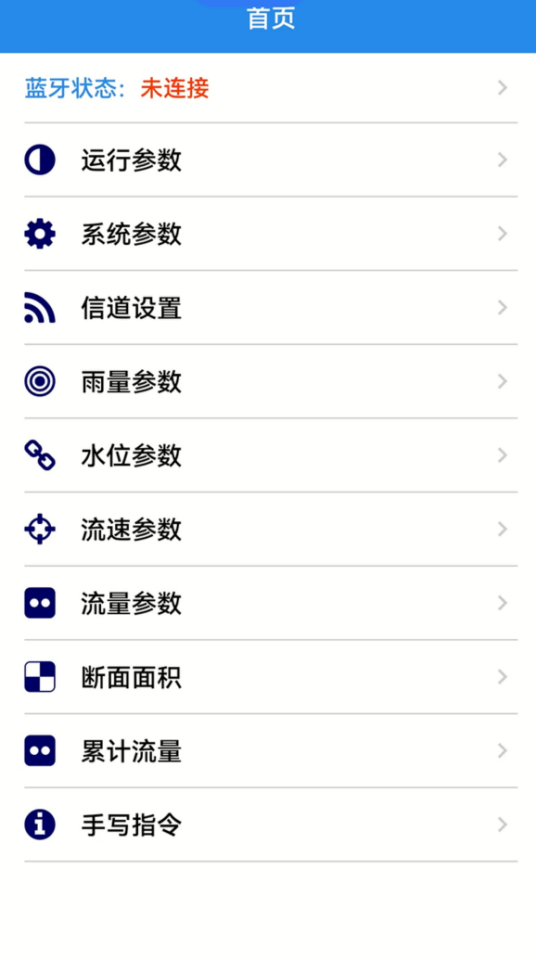
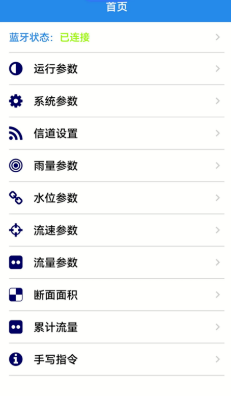
Open the Water‑Terminal APP. The home page displays Bluetooth connection status and all system functions.
When Bluetooth status shows Not Connected, tap the status field to pop‑up the Bluetooth‑device list, and tap the corresponding device Bluetooth name to establish connection.
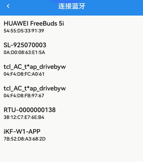
When Bluetooth status changes to Connected, you can access each system‑configuration page.
5.2 Operation Parameters
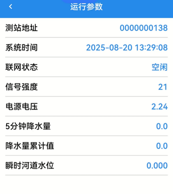
The operation‑parameters page contains 5 fixed labels and 4 variable labels.
- Station Address: The device supports 4 user channels corresponding to four station addresses. This field displays the station address of Channel 1.
- Network Status: Each of the four channels maintains independent network status. This page shows Channel 1 status; status of other channels can be viewed on the corresponding channel‑setting tab.
The four variable labels below change dynamically with sensor configurations. If the rain‑gauge function is enabled, 5‑min precipitation and cumulative precipitation will be displayed. If water‑level or flow‑velocity acquisition is enabled, corresponding measured values will be shown.
5.3 System Settings
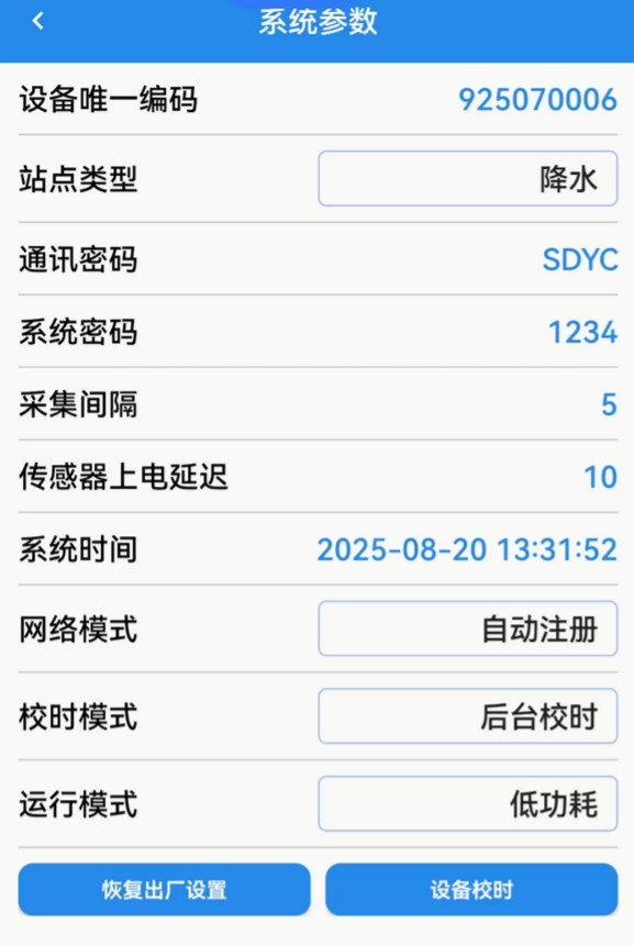
- Device Unique ID: Read‑only device identifier for manufacturer remote maintenance and cannot be modified by users.
- Station Type: Selectable options: Precipitation, River‑course, Reservoir, Sluice‑dam, Pump‑house, Tide, Soil‑moisture, Groundwater, Water‑quality.
- Communication Password: Input when required by the project. Tap the send button on the soft keyboard after input to save settings.
- Acquisition Interval: Set the data‑collection cycle (default: 5 minutes). Tap send to save after input.
- Sensor Power‑on Delay: Ignore for constant‑power‑supply sensors connected to VC terminals. For low‑power sensors connected to controlled‑power outputs, configure delay per sensor manual (default: 10 s).
- System Time: RTC synchronized time inside RTU. Tap Device Time Calibration for auto‑synchronization; manual configuration is generally unnecessary.
- Network Mode: Auto‑register / Force‑2G. The basic‑model RTU does not support Force‑2G. Do not select Force‑2G unless specially required, or network‑access failure may occur.
- Time‑calibration Mode: Default is Backend Time Sync for most scenarios. Select Primary‑Channel Sync if strict time alignment with the server is required. Only Channel 1 supports server‑side time calibration.
- Operation Mode: Low‑power / Always‑online. Default: Low‑power mode.
- Restore Factory Settings: Restore all parameters to factory defaults.
- Device Time Calibration: Manually synchronize system time.
Timed‑report debugging: After triggering this function, the device time will be set to 07:59:50 of the current day and one timed report will be triggered for debugging purposes.
5.4 Channel Settings
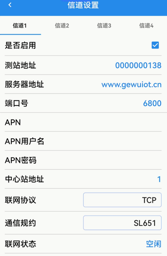
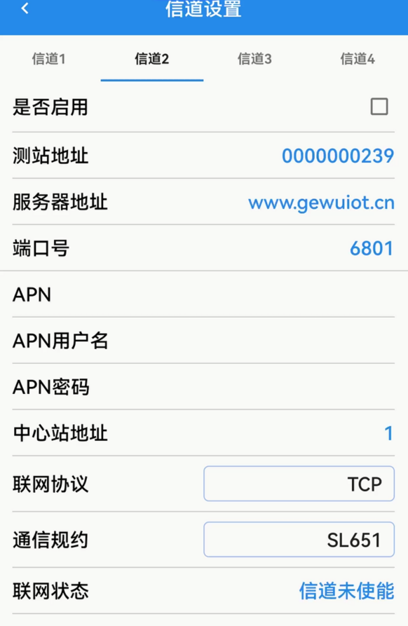
The system has four independent channels. Each channel has separate network parameters and can report data to different data centers with different station addresses and protocols. Independent APN parameters are supported, enabling simultaneous access to intranet and public network.
- Enable: Turn on / off the current channel.
- Station Address: Station ID corresponding to the current channel.
- APN: Leave blank if not required.
5.5 Rain‑gauge Settings
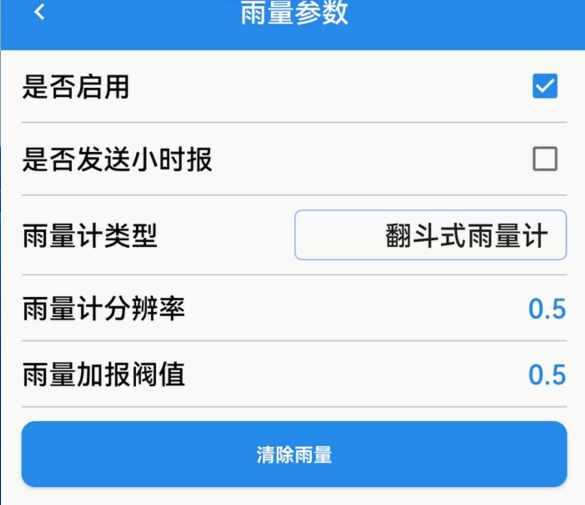
- Enable: Turn on rain‑gauge acquisition function.
- Send Hourly Report: Output 5‑min‑interval rainfall within one hour defined in SL651 protocol (element code F4). Disabled by default.
- Rain‑gauge Type: Tipping‑bucket rain gauge, weighing rain gauge, OTT WAD weighing rain gauge, OTT Pluvio2, piezoelectric rainfall sensor.
- Rain‑gauge Resolution: Rainfall value corresponding to each tipping pulse.
- Additional‑report Threshold: Set as integer multiple of rain‑gauge resolution.
- Clear Rainfall: One‑click reset for cumulative‑rainfall counter.
5.6 Water‑level Sensor Settings
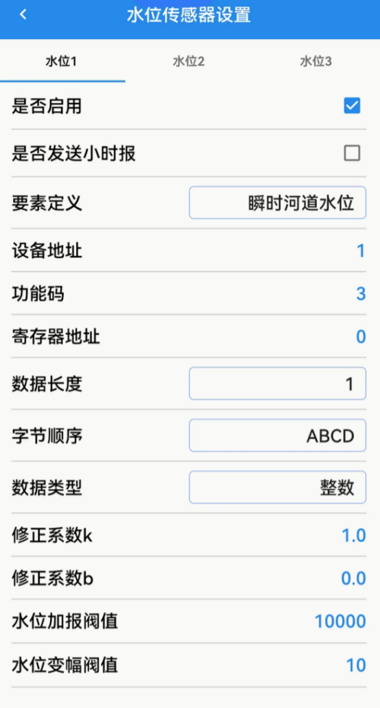
The device supports simultaneous acquisition of 3 water‑level signals, corresponding to Instantaneous‑River‑Water‑Level, Down‑reservoir‑Water‑Level and Up‑reservoir‑Water‑Level. Data will be reported according to configured labels.
- Send Hourly Report: Output 5‑min‑interval relative water‑level defined in SL651 hydrological protocol (element code F5). Disabled by default.
- Device Address: Modbus address of water‑level sensor, refer to sensor manual.
- Function Code: Commonly 3 or 4.
- Register Address: Refer to sensor manual.
- Data Length: Commonly 1 or 2, refer to sensor manual.
- Byte Order: Refer to sensor manual.
- Data Type: Refer to sensor manual.
- Correction Coefficient k: Water‑level value inside RTU is stored in mm unit. Set k=1 if raw register value is mm; set k=10 if raw value is cm. Use negative value for air‑height measurement.
- Correction Coefficient b: Water‑level base offset in mm.
Example: For radar water‑level gauge with installation height of 10 m and raw air‑height output in cm: set k=-10, b=10000. If measured air‑height =123 cm, calculated water‑level = 10000 + (-10) × 123 = 8770 mm (i.e. 8.77 m).
- Water‑level Additional‑report Threshold
- Water‑level Variation Threshold
5.7 Flow‑velocity Sensor Settings
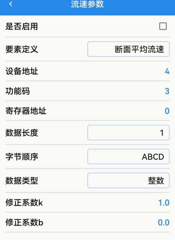
Supports one flow‑velocity sensor with two optional data labels. Parameter configuration rules are the same as those for water‑level sensors.
5.8 Flow‑sensor Settings
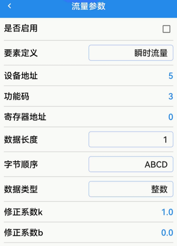
Supports one flow sensor with optional labels: Instantaneous Flow, Total Discharge / Gate‑pass Total Flow. Configure parameters following water‑level‑sensor setup rules.
5.9 Cross‑section Area Settings
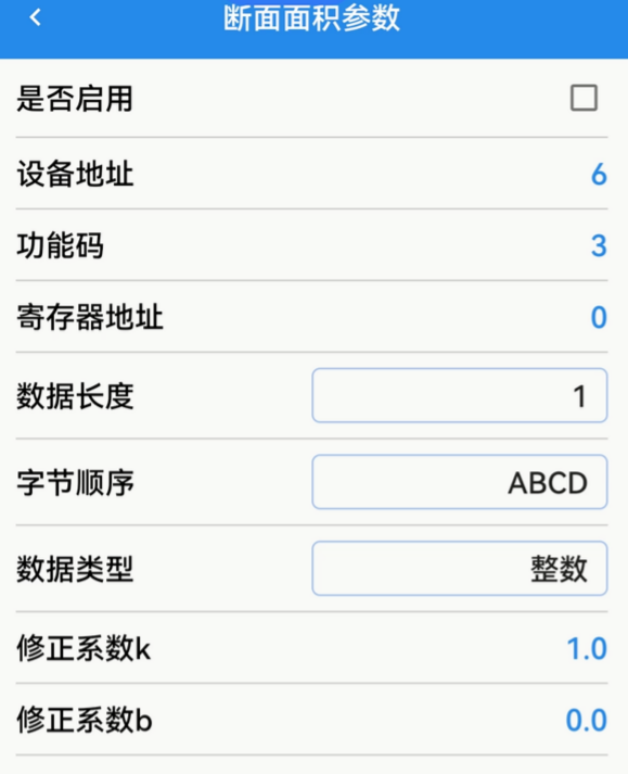
Supports one cross‑section‑area sensor. Configure parameters following water‑level‑sensor setup rules.
5.10 Cumulative‑flow Settings
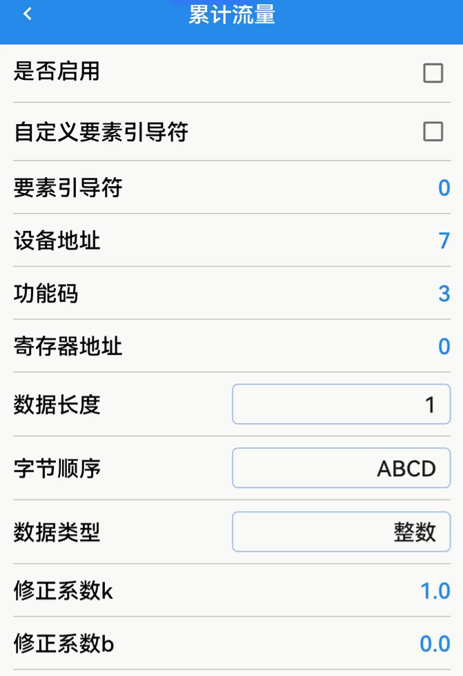
Supports custom element trigger‑flag configuration. Sensor‑related parameters follow water‑level‑sensor configuration rules.
5.11 Manual Command Input
⚠ Manual‑command input is only reserved for factory debugging and configuration and is not open to end‑users. Function Buttons: Clear / Send.