
GEWU DOCUMENTATION
GW-LS-ML Magnetostrictive Level Sensor Guide
High-accuracy continuous level measurement with calibration-free operation. Learn the product capabilities, first-use steps and support options.
What should I know about GW-LS-ML Magnetostrictive Level Sensor Guide?
High-accuracy continuous level measurement with calibration-free operation. Learn the product capabilities, first-use steps and support options.
1. Product Overview
The GW‑LS‑ML magnetostrictive level gauge is a high‑precision level‑measuring device developed based on the magnetostrictive principle. It enables continuous high‑accuracy liquid‑level measurement. Featuring simple installation requirements, calibration‑free operation and corrosion resistance, it is suitable for tank liquid‑level measurement, water‑level monitoring in irrigation districts and agricultural channels, open‑channel flow monitoring and other scenarios.
2. Technical Specifications
Basic Parameters
| Item | Parameter | Remarks |
|---|---|---|
| Product Model | GW‑LS‑ML | |
| Supply Voltage | 9~28 VDC | |
| Operating Current | 15 mA | |
| Ingress Protection | IP68 | |
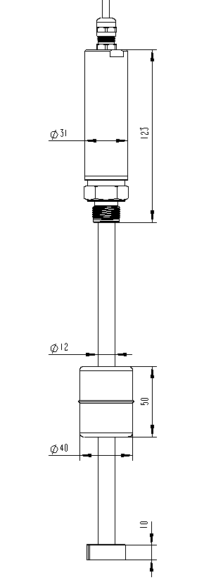
| Overall Dimension | Customizable effective length Float options: Φ52 sphere or 41×51 cylinder | |
| Operating Temperature | -40~80 ℃ | |
| Operating Humidity | 0~100 % RH (non‑condensing) | |
| Mounting Thread | M20*1.5 |
Measurement Parameters
| Item | Parameter | Remarks |
|---|---|---|
| Measuring Range | 0.1‑2 m | Customizable range per unit |
| Measurement Accuracy | ±1 mm | |
| Upper Dead Zone | 50 mm | |
| Lower Dead Zone | 50 mm |
Communication Parameters
| Item | Parameter | Remarks |
|---|---|---|
| Physical Interface | RS485 | Baud rate: 9600 |
| Communication Protocol | MODBUS | Custom non‑standard protocols supported |
3. Power‑Supply Instructions
The device accepts input voltage ranging from 9 V to 28 VDC and supports common DC power supplies. For battery‑powered low‑power applications, it is recommended that the main controller controls device power‑on and cuts off module power after data acquisition to reduce overall power consumption.
4. Protocol Description
Factory default settings: baud rate 9600, 8 data bits, 1 stop bit, no parity, Modbus protocol. Custom non‑standard protocols can be implemented for drop‑in replacement without modifying main‑controller logic.
4.1 Device Address
The default device address is 1, which can be modified via commands. If the device address is forgotten, read data using address 0xFF to identify the actual address.
When using address 0xFF, ensure only one device is connected on the bus.
4.2 Register Addresses
| Function | Register Address | Writable | Description |
|---|---|---|---|
| Liquid‑Level Data | 0x0000 | N | Unit: mm, maximum 65535 mm |
| Liquid‑Level Data | 0x0001 | N | Unit: cm; mm value rounded to centimeter |
| Offset Value | 0x03E8 | Y | Unit: mm, signed, ‑32768 ~ 32767 |
| Lower‑Range Calibration | 0x03E9 | Y | Calibrate lower measuring‑range limit |
| Upper‑Range Calibration | 0x03EA | Y | Calibrate upper measuring‑range limit |
| Device Address | 0x07D0 | Y | 1‑254 |
| Firmware Version | 0x07D1 | N | |
| Parameter Lock | 0x26AC | Y | Not for user operation under normal conditions |
| Time‑of‑Flight | 0x26AD | Y | |
| Dead‑Zone Time Value | 0x26AE | N | |
| Overflow Value | 0x26AF | Y |
4.3 Communication Examples
Read Liquid‑Level Data (level value: 2000 mm)
| Transmit | 01 03 00 00 00 01 84 0A |
|---|---|
| Response | 01 03 02 07 D0 BB E8 |
Modify Device Address (from 01 to 02)
| Transmit | 01 06 07 D1 00 02 59 46 |
|---|---|
| Response | 01 06 07 D1 00 02 59 46 |
4.4 Parameter Commissioning
You may view data and configure device parameters via commands listed in previous chapters using any serial‑port debugging tool. Operation with the visual tool Gewu Online Tool is recommended; no in‑depth knowledge of underlying Modbus frame format is required.
- Select the official template: GW‑LS‑ML Magnetostrictive Level Gauge.
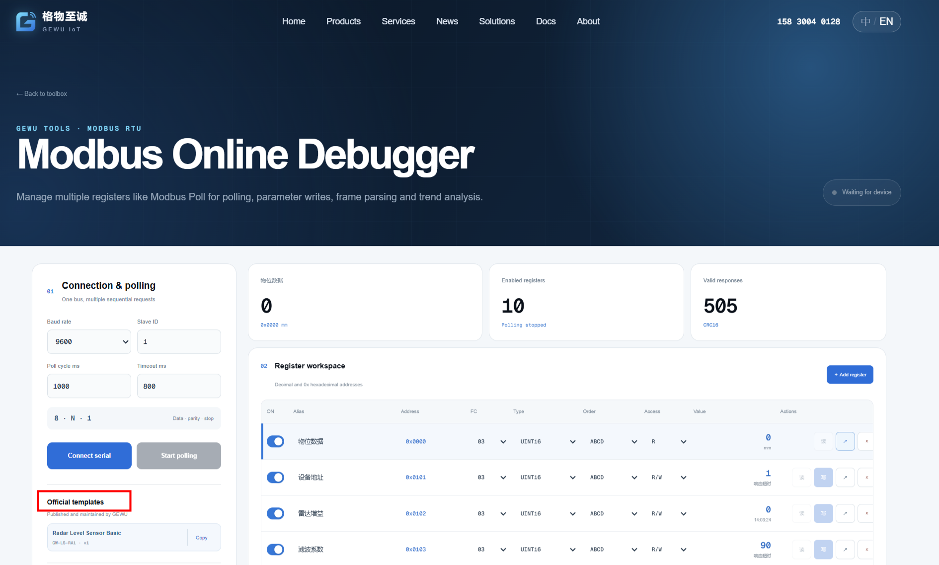
- Serial‑port parameters: 9600‑8‑N‑1.
- Click Connect Serial Port and select the serial port connected to your computer.
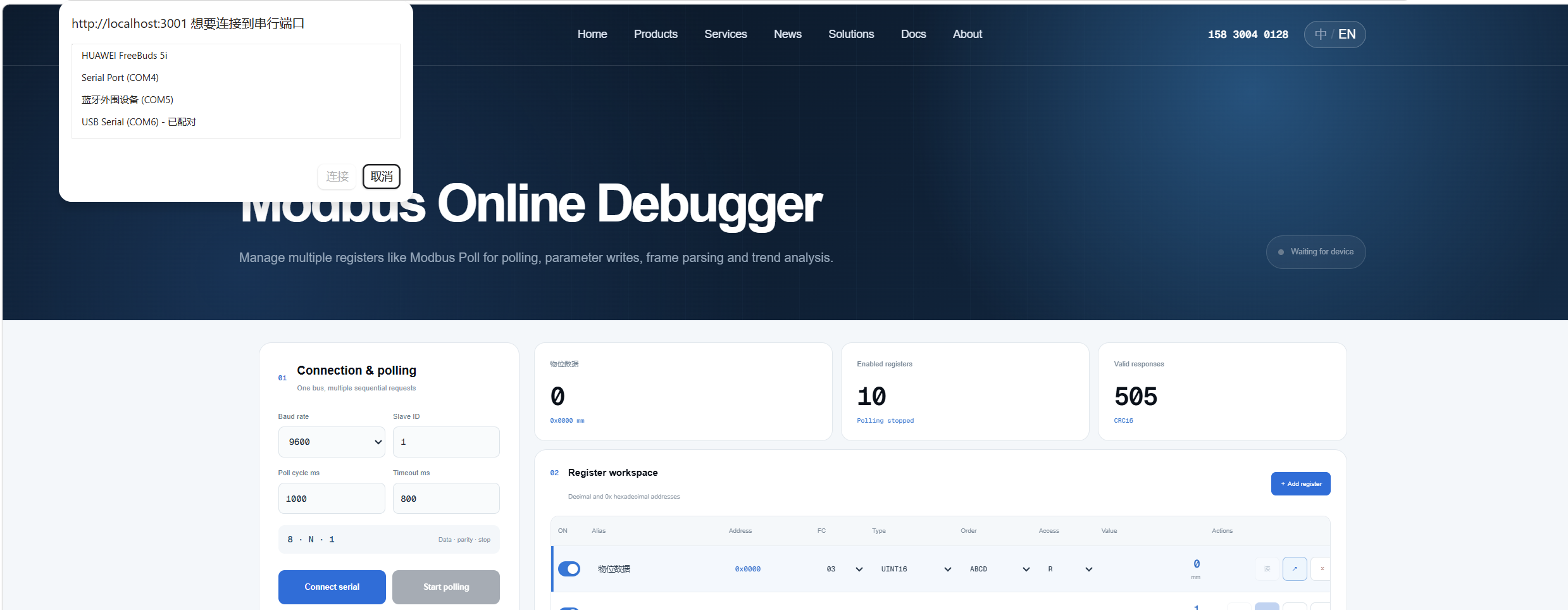
- Click Start Polling.

- To write parameters, navigate to the corresponding register, enter the value and click Confirm Write.
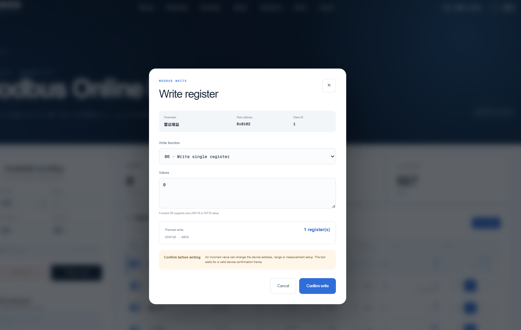 Offset Value: To apply positive or negative offset to liquid‑level readings, double‑click the value box for offset value and enter the target number. For example, enter 1000 for a uniform positive offset of 1 meter.
Lower‑Range Calibration: Move the float to the zero‑position and ensure it remains stable without shaking. Enter 0 in the value box for lower‑range calibration to complete lower‑limit calibration.
Upper‑Range Calibration: Move the float to the upper‑limit position and ensure it remains stable without shaking. Enter the corresponding upper‑limit value in the upper‑range calibration box. For instance, enter 500 for 0.5 m or 1000 for 1 m to finish upper‑limit calibration.
Modifying Device Address: Double‑click the device‑address value box and input the new address. The new address takes effect immediately. Reconfigure Modbus Poll software with the updated address afterwards.
5. Wire Harness Definition
| Wire Color | Signal |
|---|---|
| Red | VCC |
| Blue | GND |
| Yellow | RS485+ |
| Green | RS485‑ |
6. Mechanical Dimensions
8. Packing List
| No. | Item | Remarks |
|---|---|---|
| 1 | Sensor Main Unit |
Note: Printed user manual is not supplied by default. Contact the manufacturer if a hard copy is required.