
GEWU DOCUMENTATION
GW-LS-EW Electronic Water Ruler Guide
IP68 sealed electronic water ruler for canals, rivers and hydraulic structures. Learn the product capabilities, first-use steps and support options.
What should I know about GW-LS-EW Electronic Water Ruler Guide?
IP68 sealed electronic water ruler for canals, rivers and hydraulic structures. Learn the product capabilities, first-use steps and support options.
| Version | Update Content | Date |
|---|---|---|
| V1.0 | Initial release | 2022‑07‑11 |
| V1.1 | Added angle setting for tilted installationAdded elevation setting for empty‑height mode | 2022‑09‑25 |
| V1.2 | Added outline dimensions and installation diagrams | 2023‑02‑09 |
| V1.3 | Firmware upgrade, synchronized missing contents | 2024‑03‑22 |
| V1.4 | Structure & model upgrade, revised installation method | 2024‑02‑28 |
1. Product Overview
The GW‑LS‑EW is a digital sensor designed for weakly‑conductive water bodies. It detects water immersion depth via evenly‑distributed electrodes, avoiding common interferences of conventional water‑level gauges caused by temperature, water quality, conductivity and floating debris, delivering high reliability.
Equipped with an RS485 interface, it supports standard Modbus protocol; custom non‑standard protocols are available. Typical applications include hydrological monitoring, sewage treatment, smart agriculture and industrial control.
Key Features
- IP68 fully‑sealed enclosure, supports long‑term submerged operation
- Supports sloped installation; actual water depth is auto‑calculated after angle configuration
- Ultra‑low power consumption: operating power down to 0.05 W
- Fast startup: accurate measurement available 1 s after power‑on
- Abnormal‑data filtering: accurate water‑level reading under ice cover; filters interference from weeds and foreign objects
- Empty‑height mode: measures distance from sensor top to water surface
- No moving parts; eliminates risk of mechanical jamming
- Ultra‑small dead‑zone, suitable for pipes and manhole chambers
- Wide‑range power supply: 4‑28 VDC, compatible with various power sources
Application Scenarios
- Road‑side ponding monitoring (variable‑quality water, small measuring range)
- Field & channel water‑level monitoring (small range, non‑vertical mounting supported)
- Manhole water‑level monitoring (small range, fully‑submerged deployment)
- Closed‑tank water‑level measurement (fully‑submerged deployment)
2. Comparison with Similar Products
| Device Type | Remarks |
|---|---|
| Ultrasonic level meter | Poor long‑term stability, severe temperature drift, susceptible to environmental disturbance; not ideal for open‑air deployment. |
| Radar level meter | High equipment & installation‑maintenance cost; requires reflective surface and clear free space. |
| Magnetostrictive water gauge | Contains moving components; strict installation requirements; float jamming may occur. |
| Pressure‑type water‑level sensor | Poor accuracy for small ranges; vulnerable to silt and sediment. |
| Capacitive water gauge | Strongly affected by medium conductivity; accuracy degrades for variable‑composition water bodies. |
3. Technical Specifications
Basic Parameters
| Item | Parameter | Note |
|---|---|---|
| Model | GW‑LS‑EW | |
| Power Supply | 4~28 VDC | |
| Operating Current | 10 mA | |
| Ingress Protection | IP68 | |
| Operating Temperature | -40~85 ℃ | |
| Humidity | 0~100 % RH (non‑condensing) | |
| Zero Reference Line | Measuring bottom as zero point | |
| Material | Integrated aluminum‑alloy housing; nickel‑plated brass contacts; polyurethane insulation |
Measurement Parameters
| Item | Parameter | Note |
|---|---|---|
| Measuring Range | 0.1~2 m | Custom range available per unit |
| Measurement Accuracy | 5 mm / 10 mm selectable | Under 90° vertical installation |
Communication Parameters
| Item | Parameter | Note |
|---|---|---|
| Physical Interface | RS485 | Baud rate: 9600 |
| Protocol | Modbus‑RTU | Custom non‑standard protocol supported |
4. Power Supply Instructions
The sensor accepts DC input from 4 V to 28 V. It adopts internal linear power supply; operating current is independent of supply voltage. Lower supply voltage yields lower overall power consumption.
For battery‑powered low‑power applications: it is recommended that the main controller switches sensor power on before sampling and cuts power after reading data to reduce system power draw.
5. Operating Characteristics
5.1 Operating Modes
Two working modes are provided: Water‑Depth Mode (default) and Empty‑Height Mode.
- Water‑Depth Mode: sensor reports actual submerged water depth.
- Empty‑Height Mode: activated by writing a non‑zero value to reference register (
0x0102). Reports distance from sensor top to water surface.
Example: 80 cm full‑range gauge with real water depth of 5 cm. Water‑Depth output: 50 mm. After writing reference value 800 mm to register, Empty‑Height output: 750 mm.
5.2 Installation Angle
Default mounting angle is 90° (vertical installation). For sloped‑bank deployment, write the physical inclination angle between sensor and horizontal plane to installation‑angle register (0x0103). The sensor automatically computes true vertical water depth.
Example: immersed electrode length = 500 mm, installation angle = 45°. Output water depth =
500 × sin(45°) = 500 × 0.707 = 354 mm.
6. Protocol Description
Default serial parameters: 9600 baud, 8 data bits, 1 stop bit, no parity; Modbus‑RTU protocol. Custom protocol adaptation is supported.
6.1 Device Address
- Factory default address: 1, configurable via Modbus commands.
- If address is unknown: use broadcast address 0 for reading. Only one device shall be connected on bus when using address 0.
6.2 Register Address Map
| Parameter | Register Address | Data Type | Function Code | Description | Default Value |
|---|---|---|---|---|---|
| Water‑level (mm) | 0 | uint16 (read‑only) | 03 | Unit: mm | 0 |
| Water‑level (cm) | 1 | uint16 (read‑only) | 03 | Unit: cm | 0 |
| Valid Electrode Length | 256 | uint16 (read‑write) | 03 | Valid electrode count | |
| Device Address | 257 | uint16 (read‑write) | 03 | 1 | |
| Reference Baseline | 258 | uint16 (read‑write) | 03 | Unit: mm | 0 |
| Installation Angle | 259 | uint16 (read‑write) | 03 | Unit: degree | 90 |
| Resolution | 260 | uint16 (read‑write) | 03 | 5 mm / 10 mm | 5 |
| Void Parameter | 261 | uint16 (read‑write) | 03 | Factory preset | 0x1814 |
| Filter Coefficient | 262 | uint16 (read‑write) | 03 | Factory preset | 0x0A03 |
| Deep‑Water Parameter | 263 | uint16 (read‑write) | 03 | Factory preset | 0 |
| Power‑on Delay | 264 | uint16 (read‑write) | 03 | Factory preset | 3 |
6.3 Communication Examples
Read water‑level data (measured value 600 )
| Transmit | 01 03 00 00 00 01 84 0A |
|---|---|
| Response | 01 03 02 02 58 B8 DE |
Modify device address (from 01 to 02)
| Transmit | 01 06 01 01 00 02 58 37 |
|---|---|
| Response | 01 06 01 01 00 02 58 37 |
6.4 Parameter Configuration Example
You may use any serial‑port debugging tool to send commands for reading and configuring device parameters. The visual tool at https://www.gewuiot.com/tools/modbus is recommended; no knowledge of underlying Modbus messages is required.
- Select the official template: GW‑LS‑EW Electronic Water Gauge.

- Serial port parameters: 9600‑8‑N‑1.
- Click Connect Serial Port and select the serial port plugged into your computer.
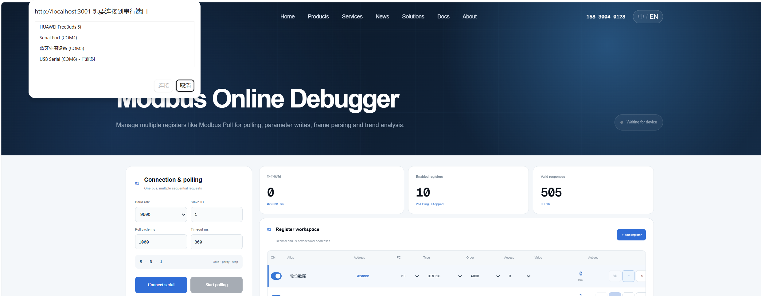
- Click Start Polling.

- To write parameters, go to the corresponding register, enter the value, and click Confirm Write.

7. Cable Wiring Definition
| Wire Color | Signal |
|---|---|
| Red | VCC |
| Black | GND |
| Yellow | RS485+ |
| Green | RS485‑ |
8. Mechanical Structure
8.1 Outline Dimensions
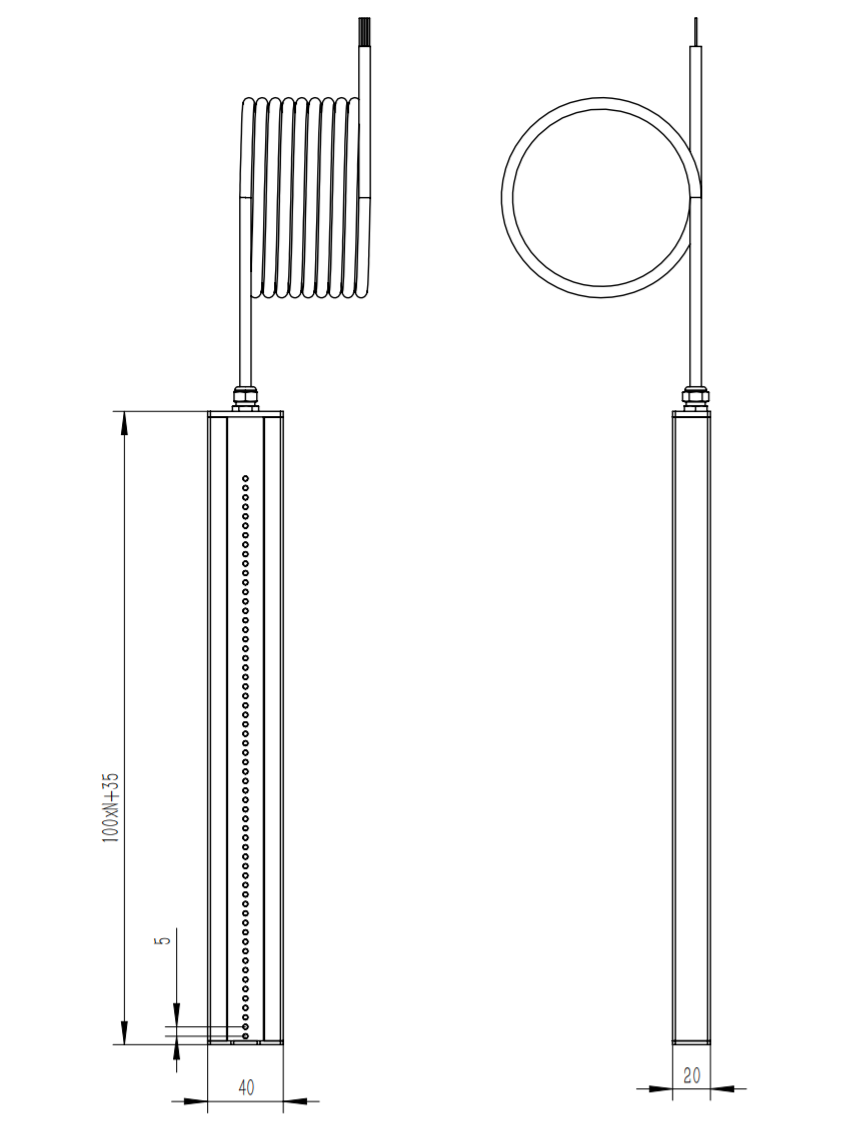
Total Length: Custom measuring length + 35 mm; Width: 40 mm; Height: 40 mm
8.2 Installation Methods
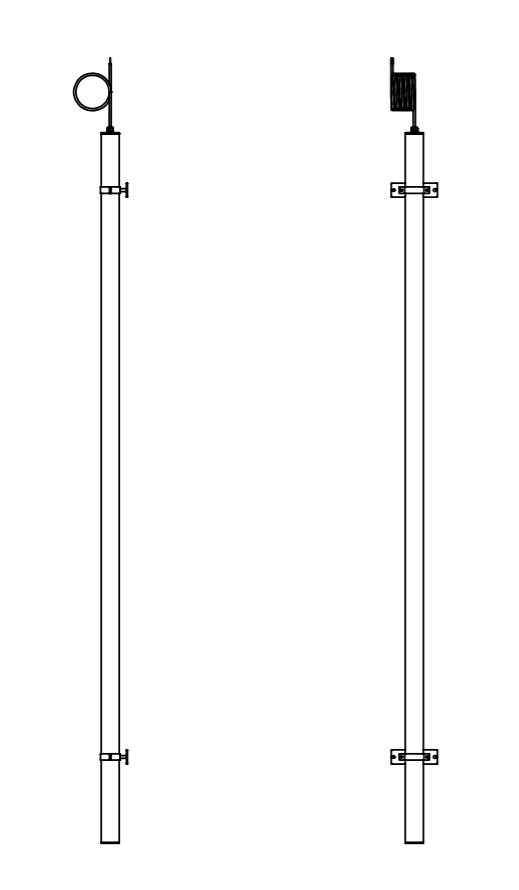
- Side‑wall mounting for channel / manhole
Use matching mounting bracket for wall‑fix installation; vertical or tilted mounting are both supported. For slope installation, configure the corresponding inclination‑angle register so the sensor calibrates depth automatically.
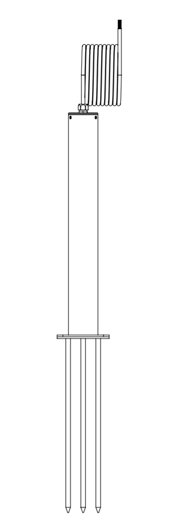
- Buried / insertion‑type mounting
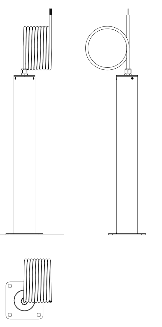
For roadside ponding, paddy‑field and other sites without available side‑wall drilling: adopt buried insertion installation, reinforced with flange base.
9. Packing List
| No. | Item | Remarks |
|---|---|---|
| 1 | Sensor Main Unit | |
| 2 | Mounting Bracket |
Note: Paper manual is not included by default. Contact manufacturer if hard‑copy document is required.