
GEWU DOCUMENTATION
GW-CO-SDI SDI12 to 485 Converter Guide
For the connection of standard SDI12 sensors. Learn the product capabilities, first-use steps and support options.
What should I know about GW-CO-SDI SDI12 to 485 Converter Guide?
For the connection of standard SDI12 sensors. Learn the product capabilities, first-use steps and support options.
1. Function Description
The module sends SDI‑12 commands to SDI‑12‑compliant sensors via its RS485 interface and returns responses over RS485, realizing conversion between RS485 and SDI‑12 interfaces. Users can connect SDI‑12 sensors through the RS485 port and develop corresponding data‑reading functions by referring to the sensor user manuals.
2. Product Features
‑ Adopts industrial‑grade RS‑485 bus interface and standard SDI‑12 physical interface & protocol. Metal housing delivers strong anti‑interference capability with transmission distance up to 1200 m. ‑ Lightning‑protection design with anti‑static interference performance. ‑ Compact form factor, suitable for diverse field conditions. ‑ Wide‑voltage input: 7‑28 VDC. ‑ Built‑in USB‑TypeC port for convenient debugging.
Application Scenarios: Compatible with meteorological, soil‑science, hydrological and environmental sensors from brands including OTT and SEBA.
3. Technical Specifications
Basic Parameters
| Item | Parameter | Remarks |
|---|---|---|
| Product Model | GW‑CO‑SDI12 | |
| Supply Voltage | 7~28 VDC | |
| Operating Current | <15 mA | |
| Ingress Protection | IP30 (Non‑waterproof; install inside control cabinet) | |
| Operating Temperature | -40~85 ℃ | |
| Operating Humidity | 0~95 % RH (non‑condensing) | |
| Overall Dimension | 60 × 66 × 18 mm | |
| Mounting Method | DIN‑rail mounting |
Communication Parameters
| Item | Parameter | Remarks |
|---|---|---|
| Physical Interface | RS485 | Baud rate 9600, 8N1 |
| Communication Protocol | MODBUS | Custom non‑standard protocols supported |
| Physical Interface | USB‑TYPEC | USB‑TTL |
| Physical Interface | SDI‑12 |
LED Indicators
| Indicator | Description |
|---|---|
| RUN | Run indicator (flashes for normal operation) |
| POWER | Power indicator (steady‑on for normal power supply) |
4. Terminal Definition
| No. | Label | Description |
|---|---|---|
| 1 | VIN | Module power supply, 7‑28 VDC |
| 2 | GND | Ground |
| 3 | A+ | RS485+ |
| 4 | B‑ | RS485‑ |
| 5 | VCC | Power output for external sensors, same potential as VIN |
| 6 | SDI12 | SDI‑12 signal line |
| 7 | GND | Ground |
| 8 | +5V | 5 V power output for external sensors, 5V@50mA |
5. Power Supply
The module accepts 7‑28 VDC input and supports common battery sources such as 2‑6‑series lithium‑ion packs and 1‑2‑series storage batteries. It will not enter sleep state after power‑on. Under full‑speed operation, power consumption is below 15 mA. For power‑sensitive systems, connect VIN to a controllable power output from the main controller to reduce overall power draw.
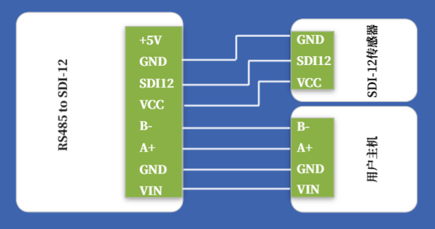
Note: No onboard voltage conversion is integrated. Wiring diagrams in subsequent chapters show sensors powered directly from VCC. If system voltage differs from sensor operating voltage, external power conditioning must be provided by user equipment. Example: If main system runs at 24 VDC but the sensor requires 12 VDC, the typical wiring cannot be used; an independent 12 V supply shall be provided for the sensor. For 5 V sensors with current ≤50 mA, the module’s built‑in +5 V output may be used for sensor power supply.
6. RS485 Interface
RS485 fixed parameters: baud rate 9600, 8 data bits, 1 stop bit, no parity.
7. SDI‑12 Interface
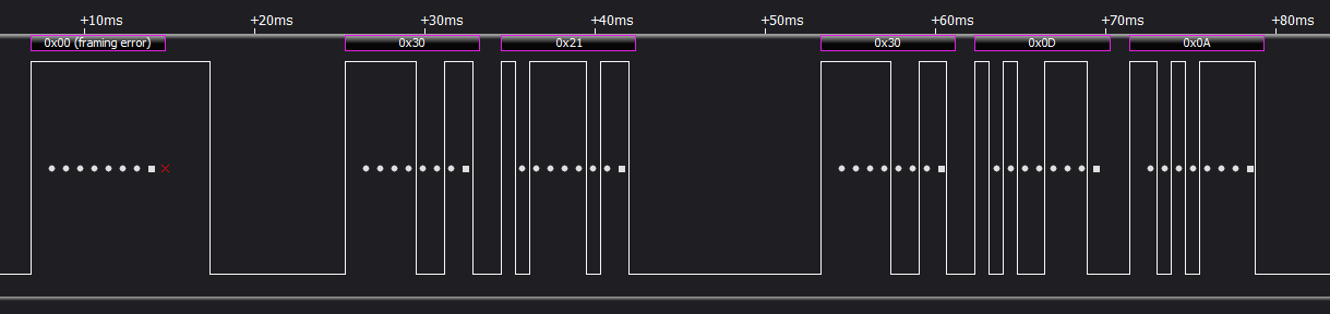
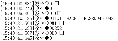
Standard SDI‑12 physical interface. The SDI‑12 protocol uses serial string‑based commands for SDI‑12 sensor connections. Develop data‑reading routines with reference to the target sensor’s documentation.
The module strictly complies with SDI‑12 protocol specifications and meets timing requirements for SDI‑12 devices.
8. Typical Hardware Wiring Diagram
9. Mechanical Dimensions
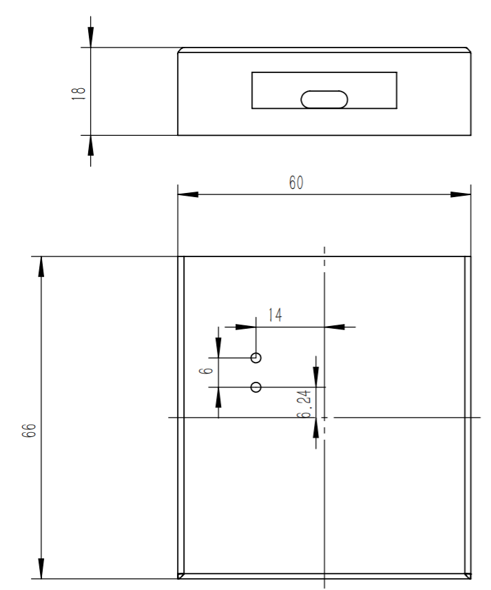
Overall dimension: 60 × 66 × 18 mm