
GEWU DOCUMENTATION
GW-LS-CL Capacitive Level Sensor Guide
Capacitive level sensor resistant to sediment, acids and alkalis with auto-calibration. Learn the product capabilities, first-use steps and support options.
What should I know about GW-LS-CL Capacitive Level Sensor Guide?
Capacitive level sensor resistant to sediment, acids and alkalis with auto-calibration. Learn the product capabilities, first-use steps and support options.
| Version | Update Content | Date |
|---|---|---|
| V1.0 | Initial version | 2021‑03‑10 |
| V1.1 | Added 2D dimension drawing | 2021‑10‑11 |
| V1.2 | Modified description of acquisition registers | 2021‑10‑13 |
| V1.3 | Corrected partial descriptive errors | 2022‑05‑24 |
| V1.4 | Added notes for operation | 2022‑06‑13 |
| V1.5 | Added installation notes | 2023‑03‑13 |
1. Product Overview
The GW‑LS‑CL is a low‑power, high‑precision capacitive level gauge featuring small‑diameter probe and ultra‑wide power‑supply range. With PTFE encapsulated housing and IP68 ingress protection, it resists acid, alkali and sediment, making it well‑suited for level measurement of various surface water and unclean water.
Measuring range covers 0.1 m to 5 m; custom range is available for individual unit.
Equipped with RS485 interface and supporting standard Modbus protocol, it also supports custom non‑standard protocols. Typical applications include water conservancy & hydrology, sewage treatment, smart agriculture and industrial control.
Product Features:
- Self‑calibration: automatic adaptation and calibration for stable long‑term output of true liquid‑level readings;
- Reliability: simple structure without moving parts, high reliability and low maintenance workload;
- Stability: readings immune to temperature, density and pressure of measured liquid;
- High Ingress Protection: superior sealing for IP68 rating;
- High Temperature Resistance: operating temperature up to 100 ℃;
- Self‑protection: comprehensive protection against over‑current, over‑voltage and reverse‑connection.
2. Comparison with Similar Products
| Device Type | Description |
|---|---|
| Ultrasonic Level Gauge | Poor long‑term stability, significant temperature drift, heavy environmental interference, not suitable for open‑air conditions. |
| Radar Level Gauge | High equipment, installation and maintenance cost; requires clear free space, not fit for narrow confined areas. |
| Magnetostrictive Level Gauge | Contains moving components, demanding installation and maintenance, prone to float jamming. |
| Pressure‑type Water‑Level Gauge | Low accuracy at small ranges, poor resistance to sediment‑laden water. |
3. Technical Specifications
Basic Parameters
| Item | Parameter | Remarks |
|---|---|---|
| Product Model | GW‑LS‑CL | |
| Supply Voltage | 9~36 VDC | |
| Operating Current | 10 mA | |
| Ingress Protection | IP68 | |
| Operating Temperature | -40~85 ℃ | |
| Operating Humidity | 0~100 % RH (non‑condensing) | |
| Zero Reference Line | Bottom of green sleeve | |
| Dead Zone | 5 mm (transparent section at bottom) |
Measurement Parameters
| Item | Parameter | Remarks |
|---|---|---|
| Measuring Range | 0.1‑5 m | Customizable per unit |
| Measurement Accuracy | ±3 mm | <300 mm |
| 1.0% F.S | 300‑700 mm | |
| 0.5% F.S | >700 mm |
Communication Parameters
| Item | Parameter | Remarks |
|---|---|---|
| Physical Interface | RS485 | Baud rate: 9600 |
| Communication Protocol | MODBUS | Custom non‑standard protocols supported |
4. Power‑Supply Instructions
The device accepts input voltage of 9‑36 VDC and supports common DC power sources. It adopts an internal linear power supply; operating current is independent of supply voltage. Lower supply voltage yields lower overall power consumption.
For battery‑powered low‑power applications, it is recommended for the main controller to control device power‑on and cut off module power after acquisition to reduce total power consumption.
5. Operating Characteristics
Advanced RF capacitive sensing circuit is adopted for core components. The internal processor performs precise temperature compensation and linear correction to generate standard electrical signals. Adopting tomography‑scan technology, the sensor automatically detects changes in dielectric constant and temperature of media, completes self‑calibration and adapts to measured media. No re‑calibration is required for diverse measurement requirements under complex field conditions. It delivers outstanding anti‑fouling, anti‑condensation and anti‑bubble performance. Rated IP68, it enables long‑term stable measurement in harsh environments.
6. Protocol Description
Factory defaults: baud rate 9600, 8 data bits, 1 stop bit, no parity, Modbus‑RTU protocol. Custom non‑standard protocols can be implemented for drop‑in replacement without modifying main‑controller logic.
6.1 Device Address
Default device address is 1, configurable via commands. If address is forgotten, read data using address 0 to identify actual device address.
When address 0 is used, ensure only one device is connected on the bus.
6.2 Register Addresses
| Parameter | Register Address | Data Type | Function Code | Description | Default Value |
|---|---|---|---|---|---|
| Level Data | 0x0000 | uint16 (Read‑Only) | 03 | Unit: mm | 0 |
| Device Address | 0x0100 | uint16 (Read‑Write) | 03/06 | 1‑254 | 1 |
6.3 Communication Examples
Read Level Data (level value: 2000 mm)
| Transmit | 01 03 00 00 00 01 84 0A |
|---|---|
| Response | 01 03 02 07 D0 BB E8 |
Modify Device Address (from 01 to 02)
| Transmit | 01 06 01 00 00 02 09 F7 |
|---|---|
| Response | 01 06 01 00 00 02 09 F7 |
6.4 Parameter Configuration Example
You may view data and configure device parameters with any serial‑port debugging tool using commands given in previous chapters. Operation via visual tool Gewu Online Tool is recommended; no deep knowledge of underlying Modbus frame format is required.
- Select the official template: GW‑LS‑CL Capacitive Level Gauge.

- Serial‑port parameters: 9600‑8‑N‑1.
- Click Connect Serial Port and select the serial‑port adapter connected to your computer.
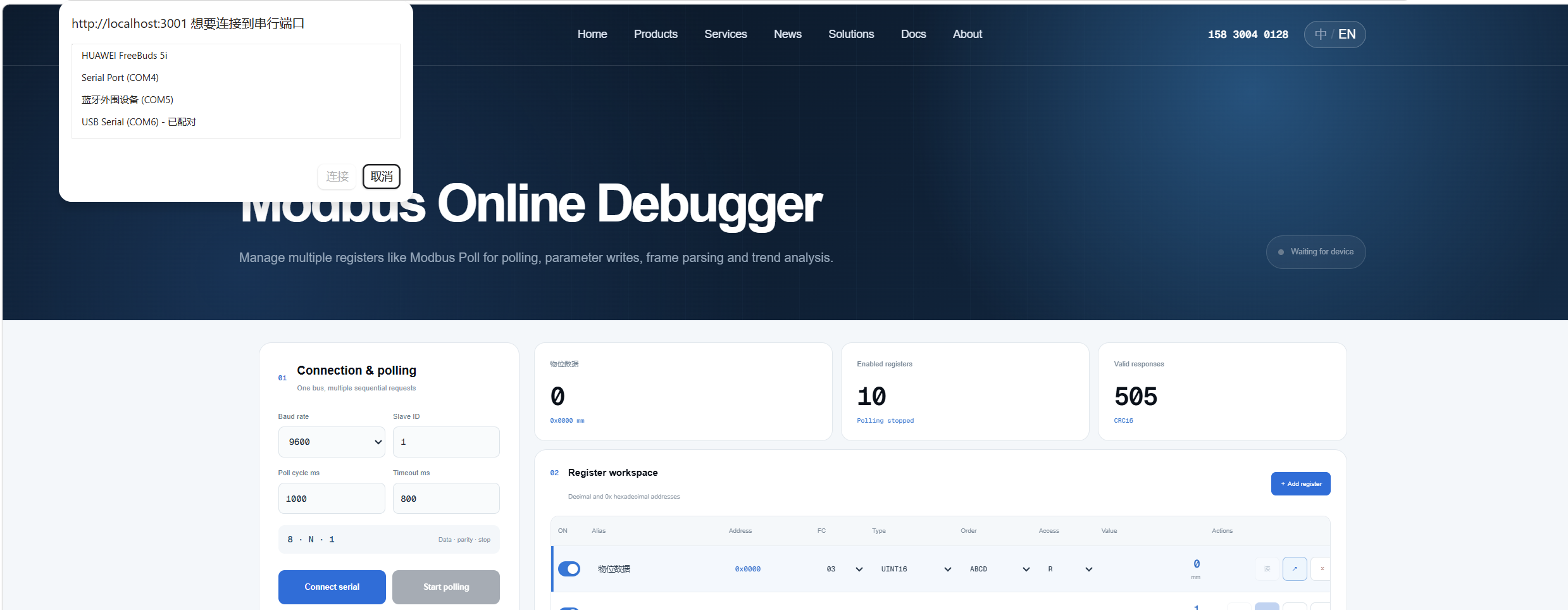
- Click Start Polling.

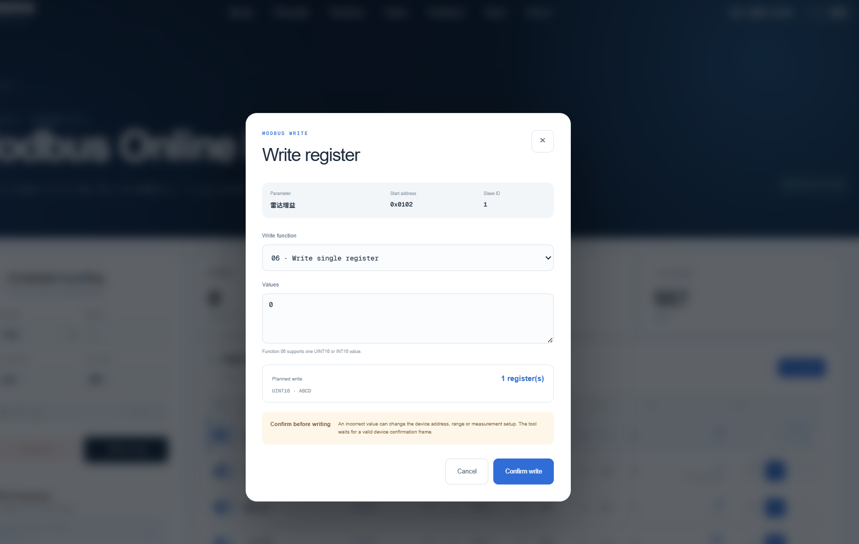
- To write parameters, navigate to the corresponding register, enter the value and click Confirm Write.
7. Wire Harness Definition
| Wire Color | Signal |
|---|---|
| Red | VCC |
| Black | GND |
| Yellow | RS485+ |
| Green | RS485‑ |
8. Mechanical Dimensions
8.1 Overall Dimensions
‑ Probe diameter: 10 mm ‑ Probe length: customizable ‑ Mounting thread: M20*1.5

8.2 Installation Precautions
Measurement is based on capacitance variation between electrode and ground. Therefore, the metal housing must be well grounded during installation. Poor grounding will introduce measurement error, which becomes more significant for longer ranges.
Recommended installation: mount sensor inside a metal tube. Weld a horizontal internal‑thread bracket (M20*1.5) inside the tube and fasten the sensor onto it. This keeps the sensor vertical and establishes reliable ground return path.
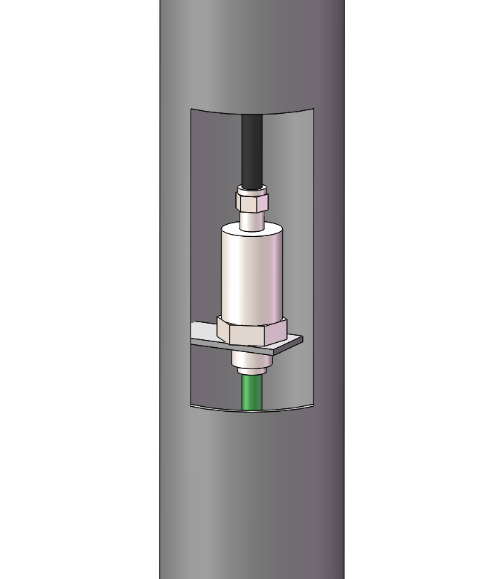
Other installation approaches are acceptable as long as metal housing achieves good grounding.
9. Packing List
| No. | Item | Remarks |
|---|---|---|
| 1 | Sensor Main Unit |
Note: Printed manual is not supplied by default. Contact the manufacturer if a hard copy is required.
10. Notes
Keep power disconnected during installation. Power on only after installation completes. Touching the sensor while powered‑on may trigger auto‑calibration and result in incorrect readings.
In operation, the metal housing of sensor shall be grounded and electrically connected to measured water body. This condition is satisfied when threaded section is mounted on grounded metal bracket. During bench test, if sensor is inserted into bottle or bucket with floating ungrounded metal housing, abnormal readings may occur. Run one wire from metal thread into water, ensuring no contact between wire and sensor probe, for valid measurement.
Capacitive level readings are affected by dielectric constant of water. Factory calibration is performed with tap water. Deviation may appear under different test conditions. The sensor features auto‑calibration: whenever water level exceeds 30 % of full‑scale range, it automatically corrects measurement accuracy against current water dielectric property. The sensor periodically updates internal parameters in field operation to sustain high‑precision performance.