GEWU DOCUMENTATION
GW-GG-PRO Product Manual SL651
Installation, interfaces, configuration and maintenance for GW-GG-PRO.
What should I know about GW-GG-PRO Product Manual SL651?
Installation, interfaces, configuration and maintenance for GW-GG-PRO.
I. Product Features
- Supports Ethernet/4G dual network, making on-site application more flexible
- 5-inch HD capacitive touchscreen for a better on-site experience
- Internal reserved battery space; optional built-in large-capacity battery to meet portable and miniaturized requirements
- Built-in Bluetooth, supports wireless wake-up by mobile APP at any time, improving O&M efficiency
- Built-in high-precision analog acquisition chip, supports 4-20mA sensors
- Supports multiple channels; each channel supports different reporting protocols and station addresses
- OTA remote upgrade
- The product has extremely low operating power consumption and can set sleep rules as required: sleep -> wake up and automatically collect -> automatically report -> sleep. It can connect to the server and report data within 5 seconds, greatly reducing average power consumption.
II. System Parameters
| Parameter | Description |
|---|---|
| Power supply voltage | 7~28VDC |
| Sleep current | 0.1mA |
| Dimensions | 17012048mm |
| Operating temperature | -25~60℃ |
| Operating humidity | 0~100% RH (non-condensing) |
| Protection rating | IP54 |
| Enclosure material | ABS |
III. Installation Instructions
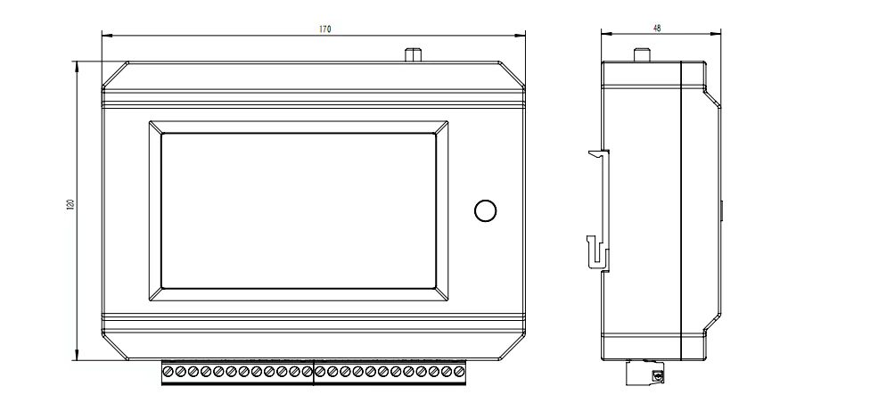
The appearance dimensions are shown in the figure below. The back has a standard DIN rail buckle and supports rail installation.
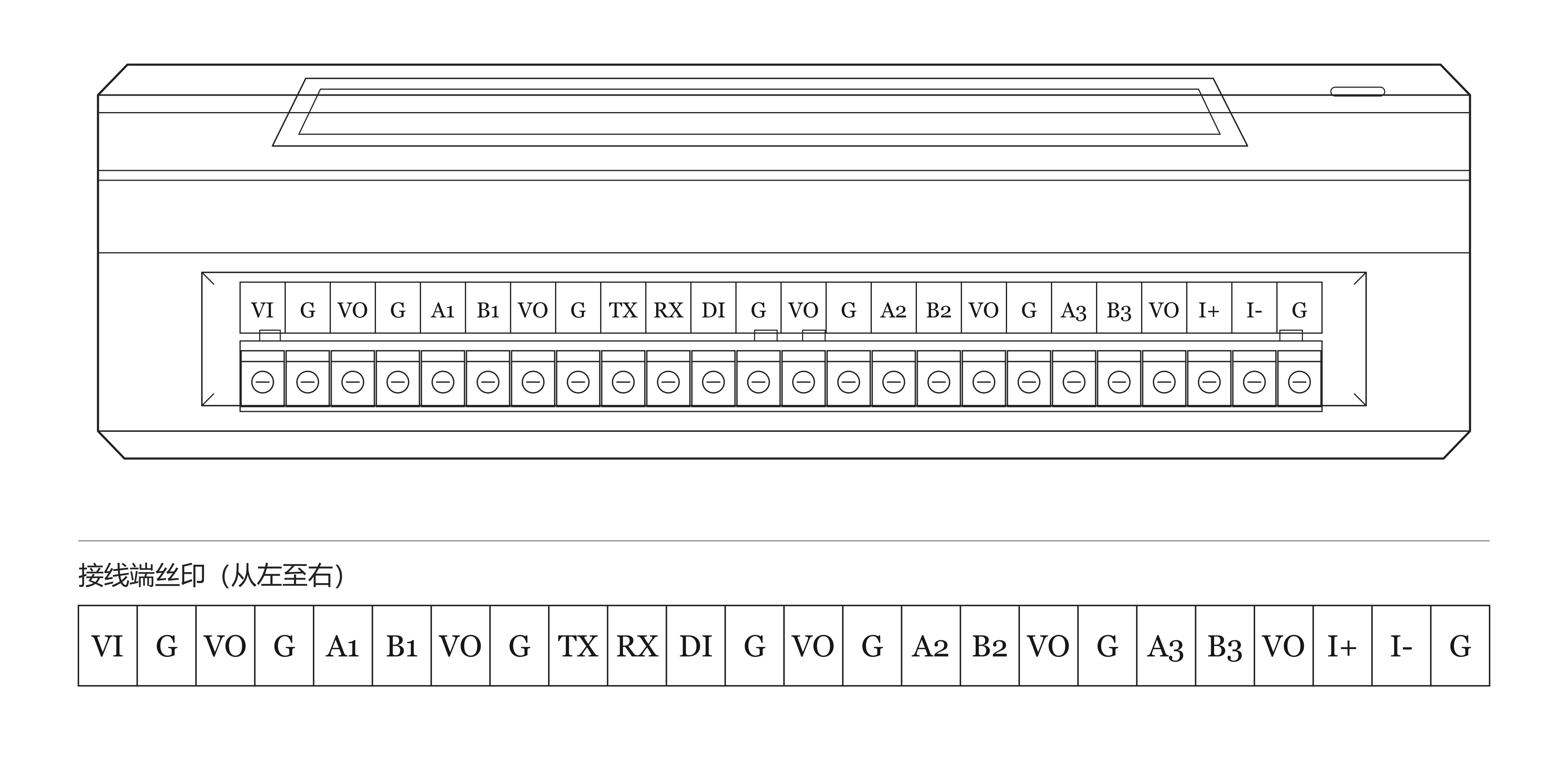
Terminal silkscreen markings:
| Marking | Description |
|---|---|
| V1 | Power positive |
| G | Power negative |
| VO | Controllable power output |
| Marking | Description |
|---|---|
| G | Power ground |
| A1 | RS485+ |
| B1 | RS485- |
| VO | Controllable power output |
| G | Power ground |
| TX | RS232 TXD |
| RX | RS232 RXD |
| DI | Digital input (pulse tipping-bucket rain gauge) |
| G | Power ground |
| VO | Same as group 1 485 controllable power supply |
| G | Power ground |
| A2 | Same as group 1 485 RS485+ |
| B2 | Same as group 1 485 RS485- |
| VO | Same as group 1 485 controllable power supply |
| G | Power ground |
| A3 | Same as group 1 485 RS485+ |
| B3 | Same as group 1 485 RS485- |
| VO | Same as group 1 485 controllable power supply |
The rain gauge interface supports tipping-bucket rain gauges, and the resolution can be set arbitrarily.
The RS485 interface supports MODBUS interface sensors such as water level, flow velocity, and flow rate. It can also connect to non-standard precipitation sensors such as OTT weighing-type rain/snow gauges and SEBA rain/snow gauges.
IV. Installation and Debugging
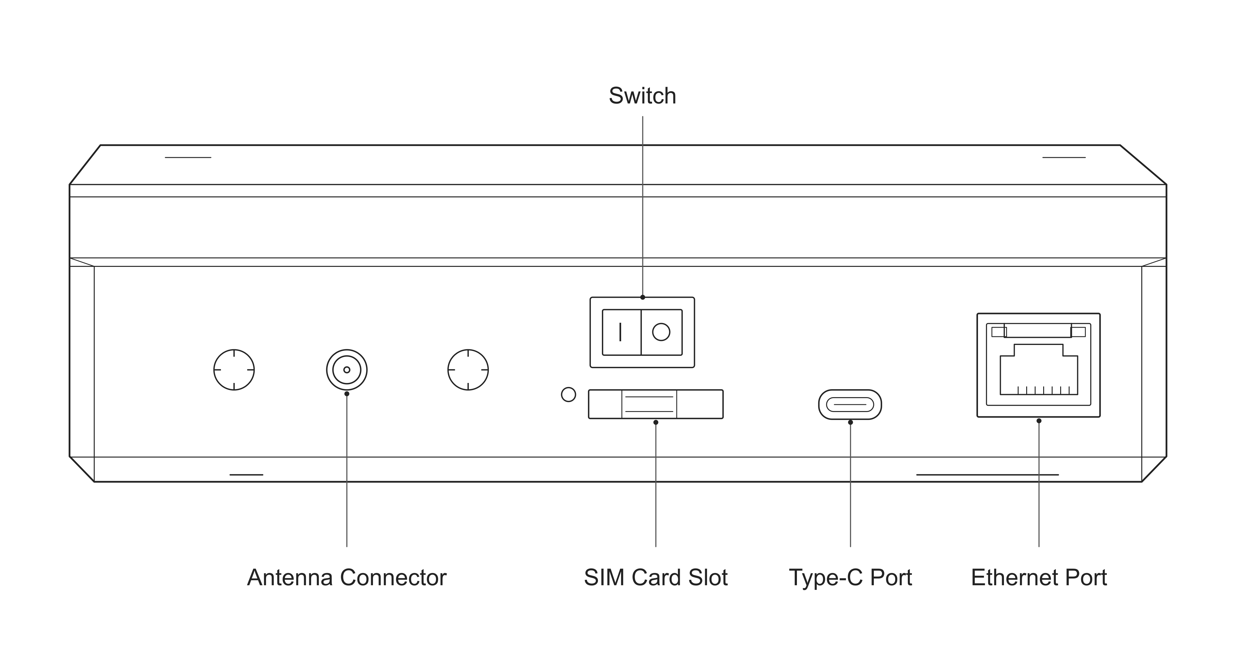
The SIM card slot is on the top of the device. Use a card pin to press the SIM card holder button to eject the SIM card holder. After installing the SIM card into the holder, insert the holder into the SIM card slot.
The antenna is on the top of the device. Tighten the antenna in the package.
If USB debugging is required, insert the USB-C cable into the TypeC interface and install the CH340 driver to debug through the serial port.
If Ethernet network access is required, insert the network cable into the Ethernet port and connect it to a router or switch.
V. Touchscreen Operation
5.1 Standby Page
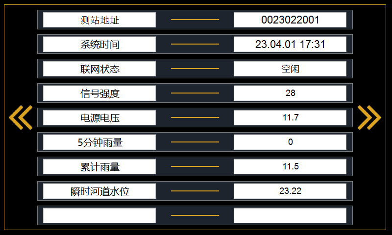
The standby page consists of five fixed value labels at the top and four variable value labels at the bottom.
Station address: Since the device supports 4 user channels, it can correspond to four different station addresses. The one displayed here is the station address of the first channel.
Network status: Since the device supports 4 user channels, each channel has a different network status. The one displayed here is the network status of the first channel. The network status of other channels can be seen on the corresponding channel settings page after logging into the system.
The four variable labels below vary according to the customer's sensor configuration. If the rainfall function is enabled, the 5-minute rainfall and cumulative rainfall will be displayed here. If the corresponding collection functions such as water level and flow velocity are enabled, the corresponding values will also be displayed here.
5.2 Login Page
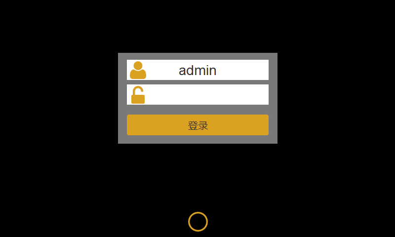
The factory default password is 1234, which can be modified on the settings page.
A password is required each time you return to the standby page.
5.3 System Settings
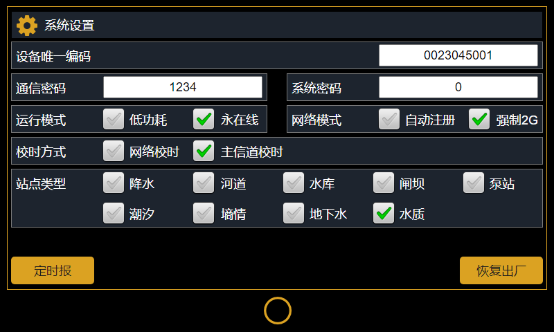
Device unique code: Serves as the unique identification code of the device. It cannot be modified by the user and is used by the manufacturer for remote device maintenance.
Network mode: Supports automatic registration and forced 2G. Unless specially required, do not configure it as forced 2G to avoid affecting network connection.
Time synchronization mode: Defaults to network time synchronization, which can meet most application scenarios. If the device time is required to be strictly the same as the server time, it can be changed to main channel time synchronization. Because server times of different channels may differ, the device only supports time synchronization from the first channel server.
Scheduled report: Clicking this button will change the device time to 07:59:50 of the current day and trigger a scheduled report for device debugging.
Restore factory: Restore default parameters.
5.4 Channel Settings
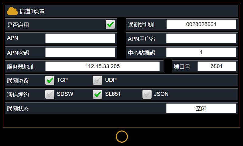
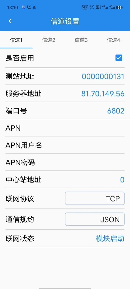
The system supports 4 channels. Each channel has independent network parameters and can report to different data centers with different station addresses and different protocols. Each channel also has independent APN parameters and supports simultaneous connection to intranet and public network.
Enable: Determines whether the current channel is enabled.
Station address: The station address corresponding to the current channel.
APN: If not used, leave blank.
5.5 Sensor Selection
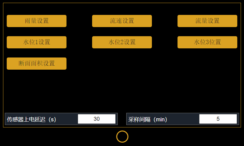
Sensor power-on delay: The time for powering the sensor. It is recommended to make this time as short as possible while ensuring the sensor can start up, so as to reduce overall power consumption.
Sampling interval: It is recommended to use the default 5 minutes. Under special circumstances, it can be reduced.
5.6 Rain Gauge Settings
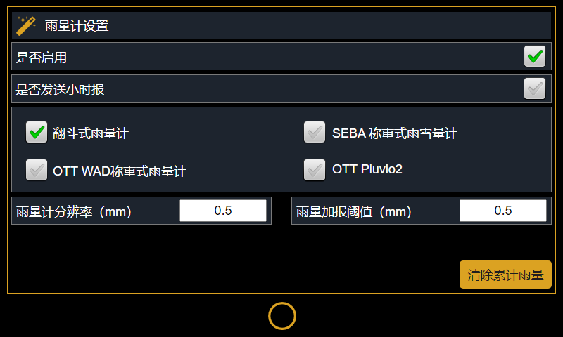
Enable: Whether to enable rainfall collection
Whether to send hourly report: Corresponds to the 5-minute interval rainfall within 1 hour in the SL651 hydrological data protocol, element code F4. Not sent by default.
Rain gauge resolution: The rainfall value corresponding to each pulse
Rainfall additional report threshold: Set to an integer multiple of the rain gauge resolution
5.7 Water Level Gauge Settings
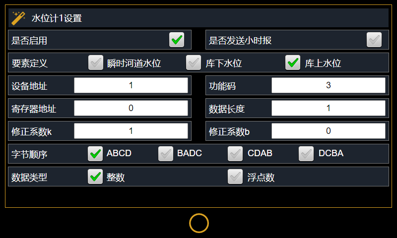
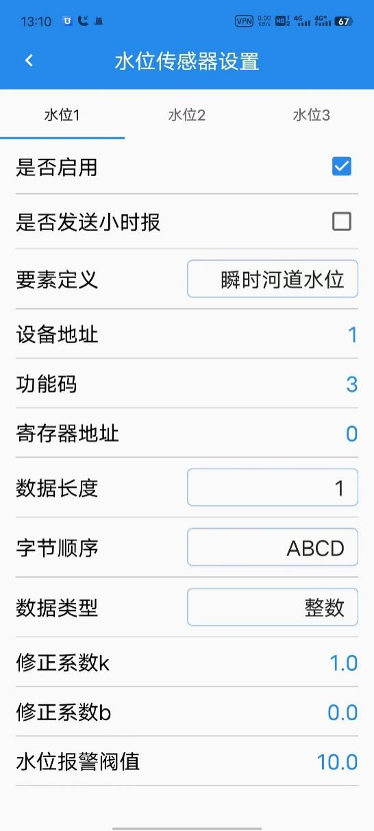
The device supports simultaneous collection of 3 water level values, each corresponding to three different label values: instantaneous river water level, downstream reservoir water level, and upstream reservoir water level. The device will report data according to the configured label values.
Whether to send hourly report: Corresponds to the 1-hour 5-minute interval relative water level in the SL651 hydrological communication protocol, element code F5. Disabled by default.
Device address: Water level sensor device address. Refer to the sensor manual for details.
Function code: Water level sensor function code, commonly 3 or 4.
Register address: Water level sensor water level register address. Refer to the sensor manual for details.
Data length: Commonly 1 or 2. Refer to the sensor manual for details.
Correction coefficient k: The RTU backend records water level in mm. If the original register value is in mm, then (k = 1); if the original value is in cm, then (k = 10). If empty height is collected, k is negative.
Correction coefficient b: Water level base value, in mm. For example, for a radar water level gauge with an installation height of 10 meters, the original output value is empty height in cm. Then set (k = - 10), (b = 10000). When the collected empty height is (123cm), the calculated water level is (10000+(- 10)*123=8770mm), corresponding to 8.77 meters.
Byte order: Refer to the sensor manual.
Data type: Refer to the sensor manual.
5.8 Flow Velocity Sensor Settings
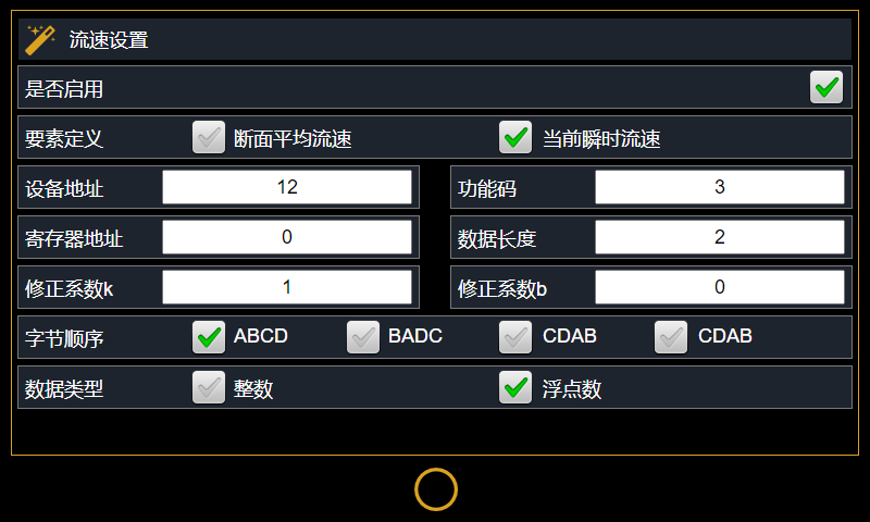
The device supports 1 flow velocity sensor, corresponding to two optional data labels.
For parameters, refer to the water level sensor settings.
5.9 Flow Sensor Settings
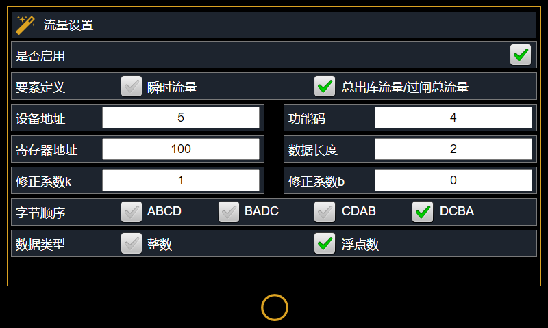
The device supports 1 flow sensor, corresponding to two optional data labels.
For parameters, refer to the water level sensor settings.
5.10 Cross-sectional Area Settings
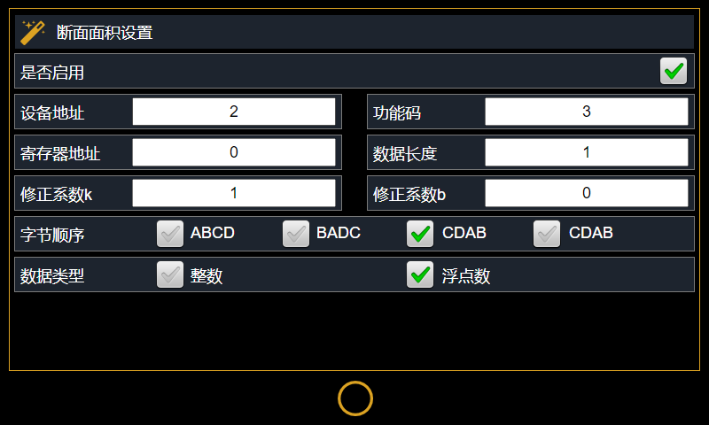
The device supports 1 flow sensor. For parameters, refer to the water level sensor settings.
VI. Bluetooth Parameter Configuration
The device has a built-in low-power Bluetooth module and is equipped with an independent Bluetooth antenna. During installation, the Bluetooth antenna and 4G antenna can be routed out of the metal cabinet at the same time.
When the device is sleeping, it still maintains Bluetooth broadcasting and can be woken up via Bluetooth while maintaining extremely low operating power consumption.
During inspections, device parameters can be viewed and configured directly from the ground, improving O&M safety and efficiency.
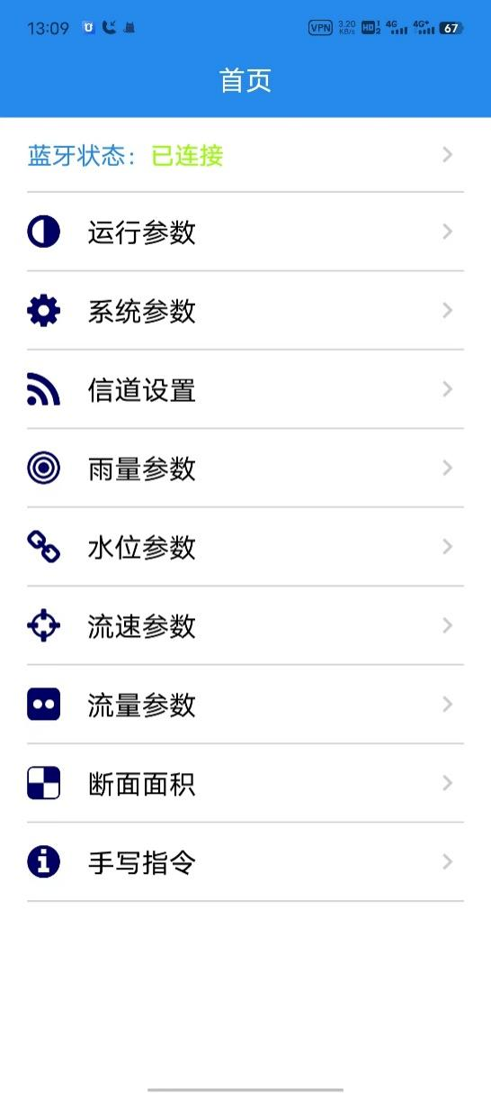
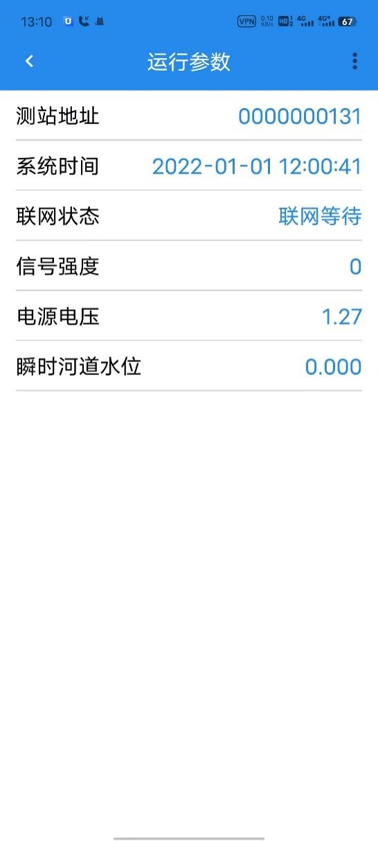
The mobile APP pages are consistent with the touchscreen. Each touchscreen page has a corresponding APP page, so they will not be described again.
Some APP pages are shown in the figure below: