
GEWU DOCUMENTATION
GW-LS-RA2 80GHz Radar Level Sensor Guide
Long-range 80GHz radar with a narrow beam for demanding installations. Learn the product capabilities, first-use steps and support options.
What should I know about GW-LS-RA2 80GHz Radar Level Sensor Guide?
Long-range 80GHz radar with a narrow beam for demanding installations. Learn the product capabilities, first-use steps and support options.
Version: V1.2
| Version | Update Content | Date |
|---|---|---|
| V1.0 | Initial release | 2022‑01‑07 |
| V1.1 | Added dual‑axis adjustable bracket; revised dimension parameters | 2023‑10‑08 |
| V1.2 | Modified wire color definition | 2024‑10‑08 |
1. Product Overview
The GW‑LS‑RA2 is an 80 GHz millimeter‑wave radar level sensor adopting FMCW radar principle. It supports maximum measuring distance up to 30 m with 5 GHz working bandwidth for high‑accuracy measurement. With IP67 ingress protection, it is suitable for outdoor field environments.
The sensor is equipped with an RS485 interface and supports standard Modbus protocol. Custom non‑standard protocols are available. Typical application scenarios include hydrological monitoring, sewage treatment, smart agriculture and object distance detection.
2. Technical Specifications
Basic Parameters
| Item | Parameter | Note |
|---|---|---|
| Model | GW‑LS‑RA2 | |
| Power Supply | 7~28 VDC | |
| Operating Current | Average: 10 mA; Peak: 40 mA | |
| Power‑on Time | 20 s | |
| Ingress Protection | IP67 | |
| Overall Dimension | 6060133 mm (with bracket) | |
| Operating Temperature | -40~80 ℃ | |
| Humidity | 0~100 % RH (non‑condensing) | |
| Zero Reference | Bottom of housing as zero point (software‑configurable) |
Measurement Parameters
| Item | Parameter | Note |
|---|---|---|
| Measuring Range | 0.1‑15 m / 0.1‑30 m | |
| Measurement Accuracy | ±1 mm | Tested on hard metallic reflective surface |
| Radar Frequency | 76G~81 GHz | |
| Beam Angle | 6° | |
| Measurement Modes | Empty‑height mode, Liquid‑level mode |
Communication Parameters
| Item | Parameter | Note |
|---|---|---|
| Physical Interface | RS485 | Baud rate: 9600 |
| Protocol | Modbus‑RTU | Custom non‑standard protocol supported |
3. Power Supply Instructions
The device accepts DC input from 7 V to 28 V. It uses an internal DC‑DC power supply: higher input voltage yields lower operating current while keeping overall power consumption roughly constant.
For battery‑powered low‑power applications: it is recommended for the host controller to power‑on the sensor before sampling and cut off power after data reading to reduce system power consumption.
4. Operating Characteristics
Factory default parameters are optimized for static level measurement for slowly‑changing targets. When target position changes abruptly, the sensor requires a certain period to synchronize to new measured values. Faster response can be enabled via configuration parameters, which shall be notified before shipment. Higher response speed will partially sacrifice measurement accuracy.
The sensor responds to Modbus commands immediately after power‑on. Nevertheless, radar internal data needs time to stabilize with a typical settling time of 5 s. For low‑power host controllers, read measured data 5 seconds after power‑on to obtain valid readings.
Default algorithm is tuned for slowly‑varying targets such as water surface. When target distance changes drastically (e.g. radar switches from facing ground to ceiling, or an obstacle is placed underneath), internal algorithm may take a much longer time (typical 30 s) to update output. You may power‑cycle the unit during testing to speed up valid value acquisition.
If fast‑moving targets need to be measured, please clarify your required response time before ordering.
The sensor evaluates echo signal strength internally. Measurements will be discarded if echo strength falls below threshold. This rarely occurs under normal conditions. Host controllers can read real‑time echo strength via Modbus for on‑site installation diagnosis.
Raw radar output is empty‑height value (distance from sensor to target). The sensor can output raw empty‑height or converted liquid‑level value. After writing installation reference baseline to register, output = reference value − empty‑height value.
- Reference value = 0: output raw empty‑height;
- Reference value > empty‑height: output difference (reference − empty‑height);
- Reference value < empty‑height: output = 0.
5. Protocol Description
Default serial settings: 9600 baud, 8 data bits, 1 stop bit, no parity, Modbus‑RTU. Custom protocol adaptation is supported for drop‑in replacement without host‑side logic modification.
5.1 Device Address
- Factory default address: 1, configurable via Modbus commands.
- If address is unknown: use broadcast address 0 for reading. Only one device shall be connected on bus when address 0 is used.
5.2 Register Address Map
| Function | Register Address | Read‑Write(Y/N) | Description |
|---|---|---|---|
| Level reading (mm) | 0x0000 | N | Unit: mm, max 65535 mm |
| Level reading (cm) | 0x0001 | N | Unit: cm, max 65535 cm |
| Device Address | 0x1000 | Y | 0~255 |
| Application Type | 0x1001 | Y | 0‑River; 1‑Tide; 2‑Well; 3‑Demo; 4‑Water Tank |
| Measurement Type | 0X1002 | Y | 0‑Level(default); 1‑Empty‑height; 2‑Distance |
| Empty‑height Reference Setting | 0X1003 | Y | Unit: mm |
| Zero‑point Offset Correction | 0X1004 | Y | Unit: mm |
| Analysis Mode | 0X1005 | Y |
5.3 Communication Examples
Read level data (2000 mm)
| Transmit | 01 03 00 00 00 01 84 0A |
|---|---|
| Response | 01 03 02 07 D0 BB E8 |
Modify device address (from 01 to 02)
| Transmit | 01 06 10 00 00 02 0C CB |
|---|---|
| Response | 01 06 10 00 00 02 0C CB |
Set empty‑height reference value (5000 mm)
| Transmit | 01 06 10 03 13 88 70 5C |
|---|---|
| Response | 01 06 10 03 13 88 70 5C |
5.4 Parameter Configuration Guide
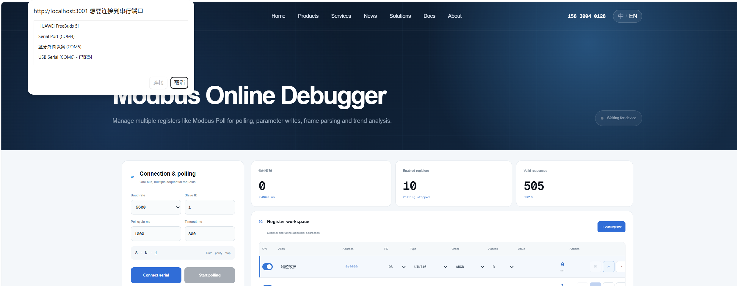
Generic serial debugging tools can send Modbus frames for reading and configuration. It is recommended to use Gewuiot Online Modbus Tool for visual operation without deep knowledge of underlying Modbus frames.
- Select official template: GW‑LS‑RA2 Radar Water Level Gauge;

- Serial port parameters: 9600‑8‑N‑1;
- Connect to the physical COM port of your computer;
- Start cyclic polling;

- To write parameters: input value in corresponding register entry and click write‑confirm.

Example for reference baseline setting: Current empty‑height = 1022 mm, set reference = 5000 mm, output =
5000‑1022 = 3978 mm. Empty‑height setting register address:0X1003(decimal 4099), use function code 06 to write value 5000. Restore factory defaults: write value 1 to register0X0107(decimal 263). Change device address: write target address to register0X1000(decimal 4096). Re‑establish serial connection afterwards.
6. Cable Wiring Definition
| Wire Color | Signal |
|---|---|
| Red | VCC |
| Black | GND |
| Yellow | RS485+ |
| Green | RS485‑ |
7. Outline Dimensions
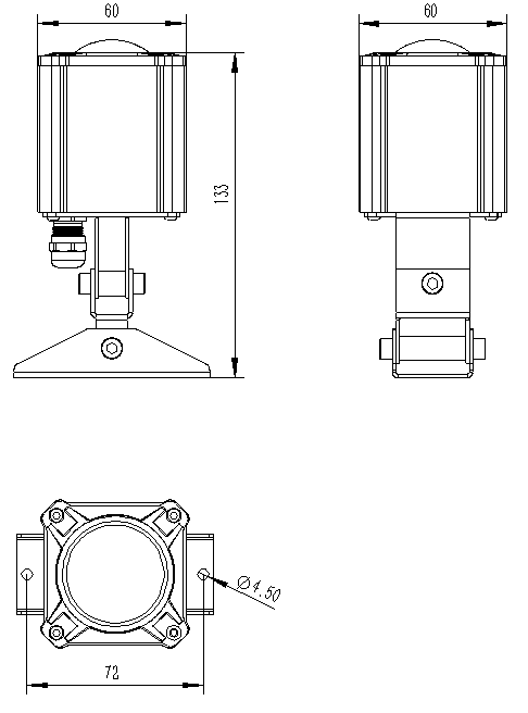
Overall dimension with dual‑axis adjustable bracket: 60*60*133 mm
Insert mechanical drawing while exporting to Word / PDF.
8. Packing List
| No. | Item | Remarks |
|---|---|---|
| 1 | Sensor Main Unit | |
| 2 | Dual‑Axis Adjustable Bracket |
Note: Hard‑copy paper manual is not included by default. Contact manufacturer if printed copy is required.