
GEWU DOCUMENTATION
GW-GC-R Remote‑controlled Intelligent Gate Hoist
Installation, control modes, water-level automation and maintenance.
What should I know about GW-GC-R Remote‑controlled Intelligent Gate Hoist?
Installation, control modes, water-level automation and maintenance.
1. Product Overview
This set of intelligent actuation‑retrofit equipment is specially designed for the intelligent upgrade of existing old sluice gates. It adopts a sluice‑body‑free retrofit solution: the original gate leaf, gate frame, civil foundation and water‑sealing structure of the user are fully reused. There is no need to dismantle or replace the sluice body. Only by adding a DC intelligent actuator, supporting IoT intelligent sluice‑gate controller, and stand‑alone solar power‑supply system, traditional old gates operated by manual hand‑crank or simple electric control can be upgraded into fully‑automatic, remotely‑accessible, auto‑measuring‑and‑controlling intelligent irrigation water‑control devices.
Inheriting mature IoT measurement‑control technologies from Gewu Zhicheng, the equipment is suitable for high‑standard farmland construction, canal‑irrigation informatization, and intelligent‑retrofit projects for small‑scale water conservancy works. It effectively addresses industry pain points of traditional sluice gates: time‑consuming & labor‑intensive manual opening/closing, high operation‑and‑maintenance costs, severe water‑resource waste, absence of data monitoring, and lack of remote control capabilities. Through lightweight and low‑cost retrofitting, it realizes digitalized, refined and unattended management for farmland water conservancy and canal water control, facilitating agricultural water‑saving & efficiency improvement and digital transformation of water conservancy.
Key Retrofit Features:
- Low Retrofit Cost: Reuse existing sluice body and civil works; no large‑scale construction, short construction period, low investment and quick returns.
- Intelligent Anti‑jamming Protection: Automatic power‑off protection against motor stall and overload to prevent equipment burnout and mechanical jamming failures.
- All‑condition Adaptive Power Supply: Passive pure solar power supply without municipal grid, suitable for off‑grid field sites.
- 4G Nationwide Cellular Remote Transmission: Wireless wiring‑free deployment, enabling remote equipment management anytime and anywhere.
- Industrial‑grade Reliability & Durability: Complete unit is dust‑proof and water‑proof with wide‑temperature operation, adapting to complex outdoor working conditions.
Application Scenarios:
- Intelligent upgrade and retrofit of high‑standard farmland
- Irrigation‑control retrofit for rural main / branch canals and field lateral canals
- Intelligent upgrade for old sluice gates and water diversion gates in off‑grid field locations
- Informatization & digital‑quality‑improvement projects for small‑scale water‑conservancy projects
2. Core Components & Function Introduction
This retrofit equipment comes without a sluice‑body structure. The complete system consists of four core units: DC intelligent actuator, IoT intelligent controller, solar power‑supply system, and optional water‑level sensing module. It adopts modular integrated design, featuring high compatibility, easy installation and simple operation & maintenance.
2.1 Multi‑mode Intelligent Control Functions
The system supports free switching among three modes: remote cloud‑based control, local manual / electric control, and automatic water‑level linkage control, fully meeting on‑site management requirements and realizing unattended intelligent operation‑and‑maintenance.
- Remote Cloud‑based Control: Supports WeChat Mini‑Program, PC cloud platform and API docking. Real‑time viewing of equipment status, battery voltage, upstream‑and‑downstream water‑level data; one‑click remote gate opening / closing and precise opening‑degree adjustment for round‑the‑clock unattended management.
- Multiple Local‑control Options: Equipped with physical operation buttons, optional touch screen and low‑power Bluetooth for local commissioning. An emergency manual hand‑crank is also retained. Manual gate operation is available upon power failure, network anomaly or equipment fault to guarantee continuous irrigation water supply.
- Automatic Water‑level Regulation: Supports dual‑mode linkage control of upstream‑water‑level and downstream‑water‑level. After managers preset upper‑and‑lower water‑level threshold values, the system automatically adjusts gate status and opening degree according to real‑time water levels to achieve on‑demand water control and precise water saving.
2.2 High‑efficiency & Energy‑saving Passive Power‑supply Design
- Stand‑alone Solar Power‑supply System: Combined high‑power photovoltaic panel and large‑capacity gel energy‑storage battery, paired with intelligent charge‑discharge management module. No external municipal power supply required. It independently completes daytime charging and nighttime voltage‑stabilized power supply, and ensures stable operation through successive rainy days, completely solving difficulties of power access and high wiring cost for field sluice positions.
- Ultra‑low‑power Drive: Equipped with high‑performance industrial DC low‑power motor; gate opening‑closing speed>4 mm/s with smooth & efficient actuation and extremely low standby power consumption. Balances operating efficiency and long‑term energy‑saving performance for round‑the‑clock low‑power on‑duty scenarios.
2.3 Highly‑reliable Durable Protection Design
- Reliable Equipment Materials: Control cabinet adopts spray‑painted galvanized sheet‑metal; transmission accessories are made of stainless steel for corrosion resistance and aging resistance, adapting to complex outdoor environments such as extreme cold, high temperature, saline‑alkali and humid conditions.
- Multiple Intelligent Protections: Multi‑layer protections including motor overload & stall protection, over‑charge / over‑discharge protection, short‑circuit protection, lightning‑protection grounding, water‑proof & dust‑proof features, effectively avoiding equipment damage, water‑leakage jamming and circuit failures to guarantee long‑term stable equipment operation.
2.4 Precise Monitoring & Intelligent Data Management
- Sensor Expansion Adaptation: Optional accessories such as electronic water‑level gauge, radar water‑level gauge and flow meter can be deployed to collect core data including upstream‑and‑downstream water levels and irrigation flow in real‑time, providing accurate data support for smart irrigation and water‑conservancy dispatching.
- Full‑dimension Data O&M: Automatically stores equipment operation data, gate open‑close records, water‑level variation data and battery‑voltage data. Supports historical‑data query & export. Alarm notifications will be pushed for low‑battery, equipment fault and network anomaly conditions, greatly reducing manual operation‑and‑maintenance costs.
3. Core Technical Specifications
3.1 Basic Parameters
| Item | Parameter |
|---|---|
| Equipment Model | GW‑GG‑R (Retrofit‑type Intelligent Actuation Measurement‑control Equipment) |
| Driving Mode | Industrial‑grade DC low‑power motor drive |
| Power‑supply Mode | Solar photovoltaic + gel energy‑storage battery (power & capacity configurable on demand) |
| Operating Current | 0.02 A (standby) |
| Ingress Protection | IP65 |
| Operating Temperature | ‑40 ℃ ~ 70 ℃ (excluding optional display screen) |
| Display Function | 7‑inch IPS capacitive touch screen (optional on demand) |
| Equipment Material | Spray‑painted galvanized sheet‑metal cabinet, stainless‑steel transmission accessories, water‑proof sealing structure |
| Gate Actuation Speed | >4 mm/s |
3.2 Communication Parameters
| Item | Parameter | Remarks |
|---|---|---|
| Cellular Network | 4G nationwide cellular network | Wiring‑free wireless, round‑the‑clock data transmission |
| Near‑field Communication | BLE low‑power Bluetooth | Local wireless commissioning and parameter configuration |
| Physical Interface | RS485 | Baud rate: 9600 8N1 |
| Communication Protocols | MODBUS, TCP, MQTT, JSON | Customizable industry‑specific protocols |
3.3 Button‑function Definition
| Button | Function |
|---|---|
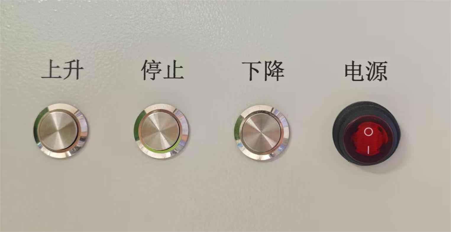
| Power Key | Equipment power‑on / power‑off, emergency power‑off stop |
| UP Key | Open sluice gate, increase opening degree |
| STOP Key | Immediate halt of gate movement |
| DOWN Key | Close sluice gate, decrease opening degree |
4. Retrofit Optional Parameters (Basis for Quotation)
This equipment is a lightweight customized retrofit product with no fixed sluice‑body dimensions. It is fully compatible with specifications of existing user‑owned sluice gates. Quotation requires confirmation of parameters listed below:
| No. | Parameter | Example | Remarks |
|---|---|---|---|
| 1 | Existing Sluice‑gate Dimension | 600600 mm, 500500 mm | Reuse original sluice body, no replacement required |
| 2 | Maximum Gate Opening Stroke | 200 mm, 500 mm | Matches actuator stroke |
| 3 | Touch‑screen Configuration | Required / Not required | Optional for on‑site visual operation |
| 4 | Optional Sensor Equipment | Electronic water‑level gauge, radar water‑level gauge | Essential for water‑level monitoring and automatic water control |
| 5 | Solar‑system Specification | Standard / Enlarged capacity | Adapt to different rainy‑day endurance requirements |
5. Installation Procedures (Special for Sluice‑body‑free Retrofit)
This retrofit does not modify original sluice body, water‑sealing structure or civil foundation. Only installation and commissioning of actuator, controller, power‑supply system and sensing equipment are required for simple and efficient construction.
5.1 Pre‑installation Preparation
Technical Disclosure
Get familiar with retrofit scheme, equipment parameters and installation specifications. Verify original sluice‑gate specifications, actuation stroke and mounting‑base positions. Confirm equipment installation points, fixing methods and cable routing paths.
Tools & Materials Preparation
‑ Tools: Spirit level, spanners, screwdrivers, multimeter, lifting aids, waterproof tools ‑ Materials: Fixing bolts, gaskets, waterproof cables, waterproof connectors, grounding wire, sealant, etc.
Foundation Inspection
Clear debris and rust from original sluice‑gate actuation base and mounting platform. Inspect flatness and firmness of base to satisfy mounting requirements for actuator and control equipment.
5.2 Core‑equipment Installation
Actuator Fixed‑mounting
Secure the DC intelligent actuator steadily onto the original sluice‑gate actuation base. Calibrate equipment levelness and verticality. Ensure precise alignment between actuator transmission structure and original sluice‑gate drive end with uniform clearance; guarantee jamming‑free and offset‑free gate actuation. Tighten fixing bolts symmetrically to avoid uneven stress.
Intelligent‑controller Installation
Mount the measurement‑control controller in rain‑proof, sun‑shaded and operator‑friendly location, away from ponding and direct sunlight. Ensure adequate ventilation & heat dissipation and firm installation without shaking.
Solar‑system Installation
Fix photovoltaic panels at well‑illuminated obstruction‑free position and adjust for optimal light‑collection angle. Seal energy‑storage batteries inside waterproof cabinet for water‑proof & moisture‑proof protection. Connect charge‑discharge cables and guarantee firm connections with intact insulation.
Sensor‑equipment Installation
Install water‑level sensors as required at designated upstream‑and‑downstream monitoring positions. Ensure stable submersion of sensing probes without obstructions for accurate data acquisition.
5.3 Electrical Wiring & Protection
Strictly follow wiring diagrams to connect actuator control cables, controller signal cables (RS485), power‑supply cables and sensor cables. All cable interfaces shall be sealed with waterproof connectors and conduits to prevent rainwater ingress. Metal equipment housings shall be reliably grounded with grounding resistance ≤4 Ω to implement lightning‑proof and anti‑static protection.
5.4 Equipment Commissioning & Testing
Manual Commissioning
Switch to manual mode and operate via emergency hand‑crank to test gate movement smoothness; check for abnormal noise or mechanical jamming and confirm sound mechanical transmission.
Local Electric Commissioning
Power‑on the power‑supply system. Test full‑open, full‑close, start‑stop gate motions via physical buttons and touch‑screen. Calibrate zero‑point and full‑range of opening‑degree sensor and verify validity of emergency‑stop function.
Remote & Automatic Commissioning
Bring equipment online. Test remote gate actuation and opening‑degree adjustment functions via Mini‑Program and cloud platform. Set upper‑and‑lower water‑level threshold values to test water‑level‑linkage automatic regulation. Verify data‑transmission accuracy and equipment response speed. Simulate motor stall and low‑battery scenarios to validate overload‑protection and alarm‑trigger functions.
5.5 Acceptance & Hand‑over
- Functional Acceptance: Inspect gate actuation stability, control accuracy, water‑proof protection, remote‑control performance, automatic water‑control logic and alarm functions. Confirm absence of water‑leakage, jamming or other faults.
- Document Hand‑over: Deliver equipment user manual, installation‑commissioning records, parameter‑configuration report and warranty documents.
- Operation‑and‑maintenance Training: Train operators on daily operation, parameter setting, dirt‑removal maintenance and basic fault troubleshooting.
⚠️ Installation Precautions
- Avoid bumping equipment housing, cable interfaces and sensor probes during installation to prevent hardware damage.
- Implement rain‑proof & water‑proof measures for rainy‑season construction; strictly prohibit electric‑component moisture ingress.
- Keep personnel away from moving transmission parts of sluice‑gate during commissioning to avoid mechanical injury.
- Core communication and commissioning parameters are factory‑preset. Non‑professionals shall not modify them arbitrarily.
6. Equipment Operation Guide
6.1 Remote‑control Operation
WeChat Mini‑Program Control
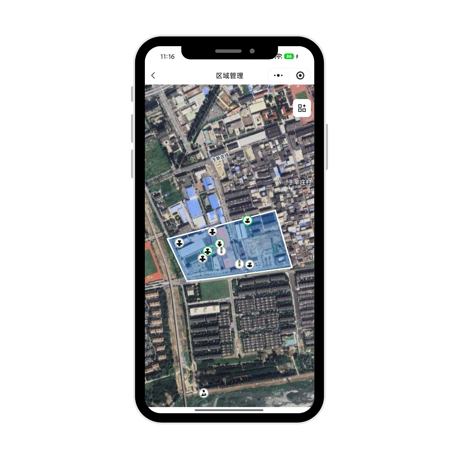
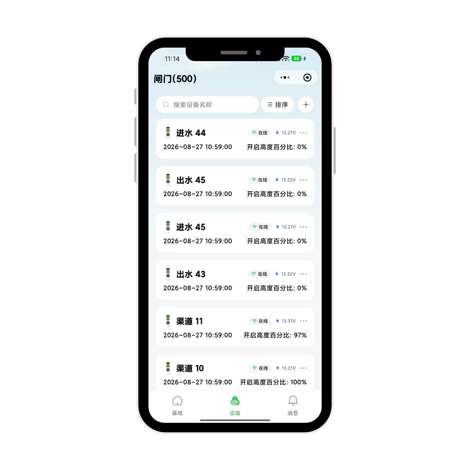
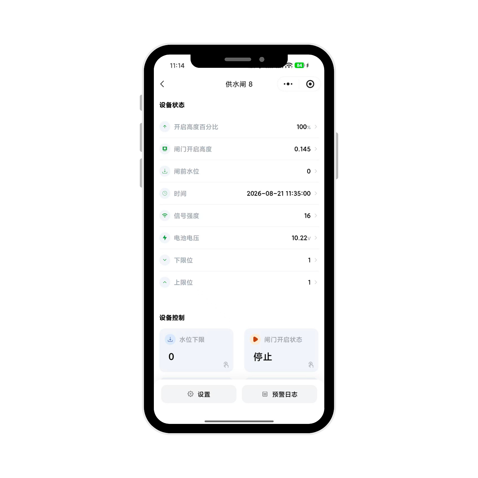
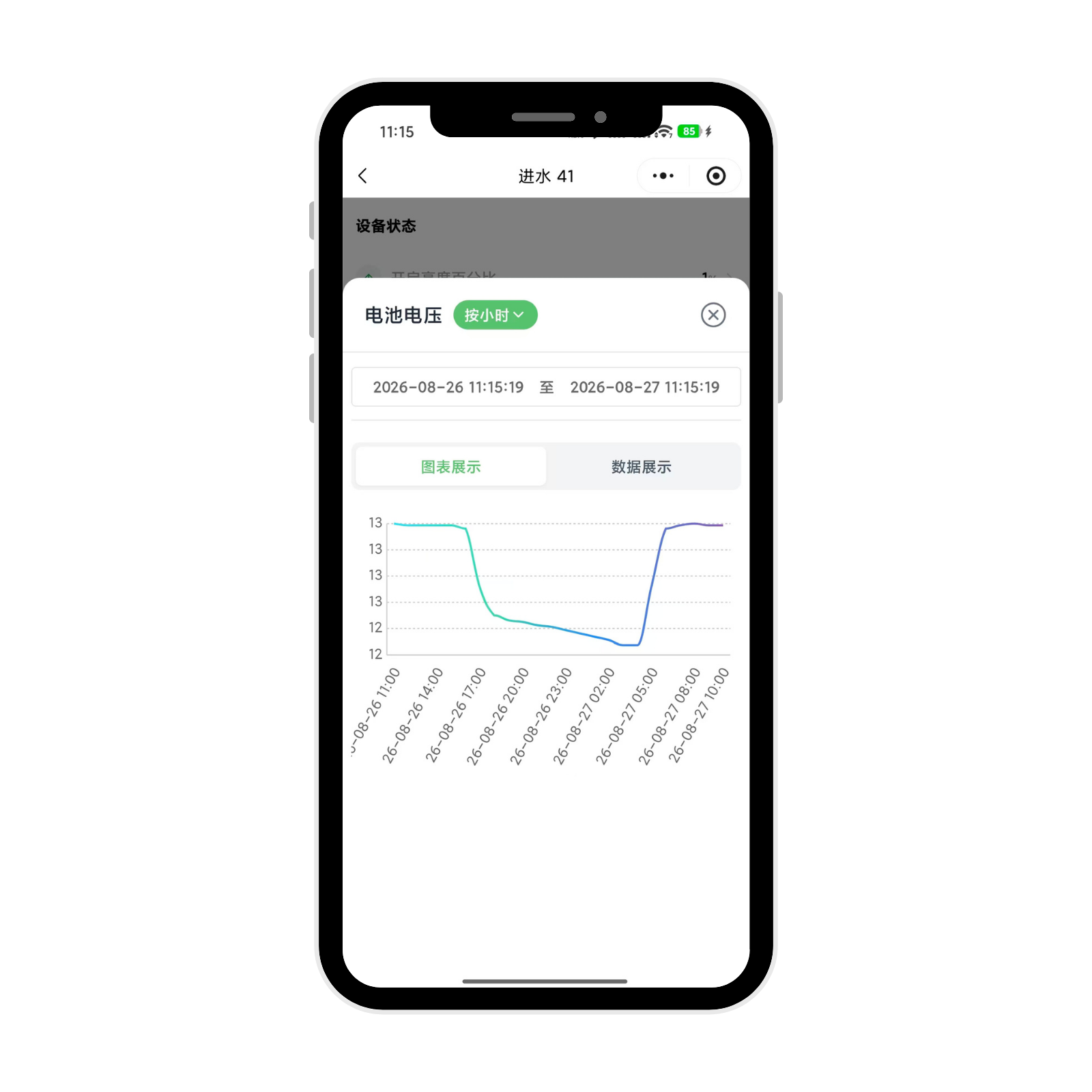
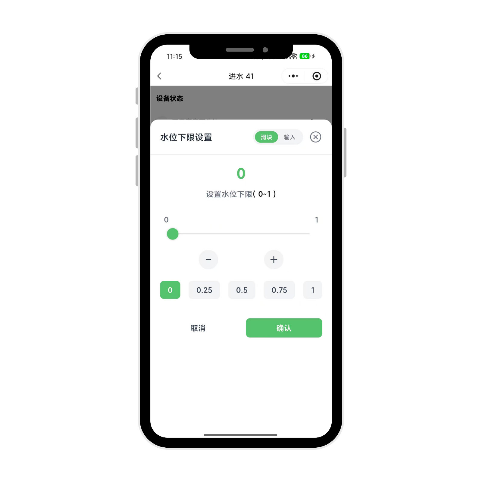
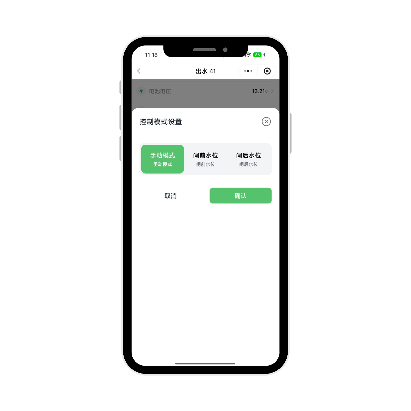
Supports dual‑browsing modes: plot mode and list mode. Edit field‑plot information and enable quick equipment search. Real‑time monitoring of equipment operating status, battery voltage, signal strength, upstream‑and‑downstream water‑level data. Under manual mode: tap Open / Stop / Close for gate actuation. Under automatic mode: slide to set upper‑and‑lower water‑level thresholds; the system automatically adjusts gate opening‑degree. Supports query and trace‑back for historical operating records, actuation logs and alarm logs.
PC Cloud‑platform Control
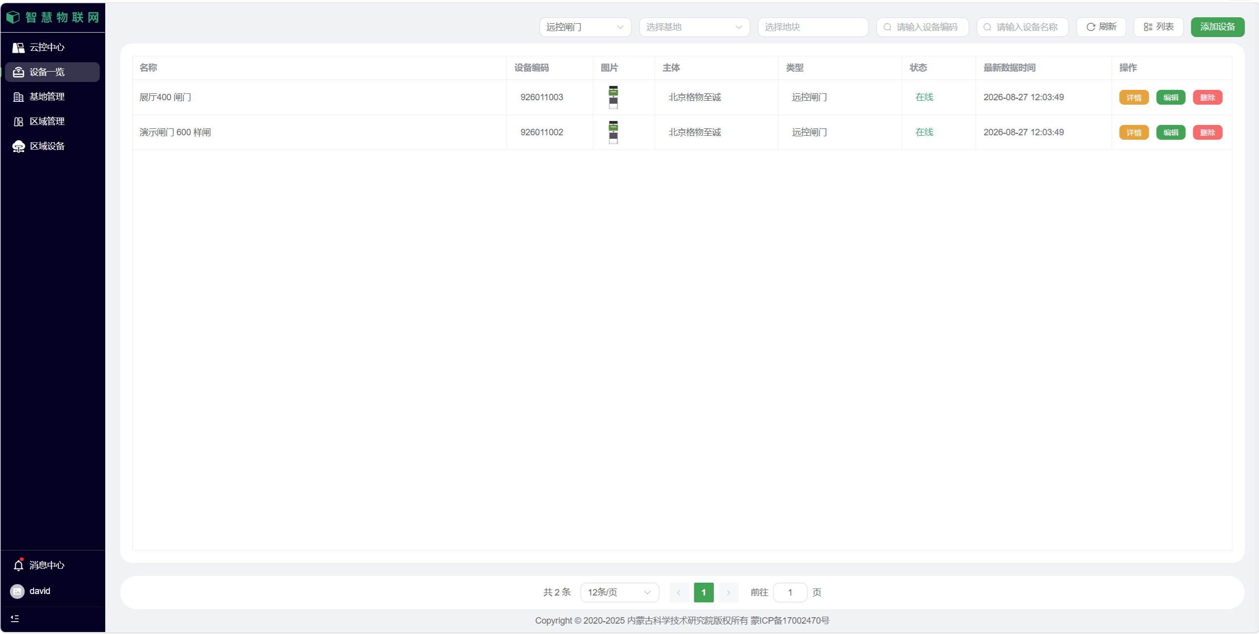
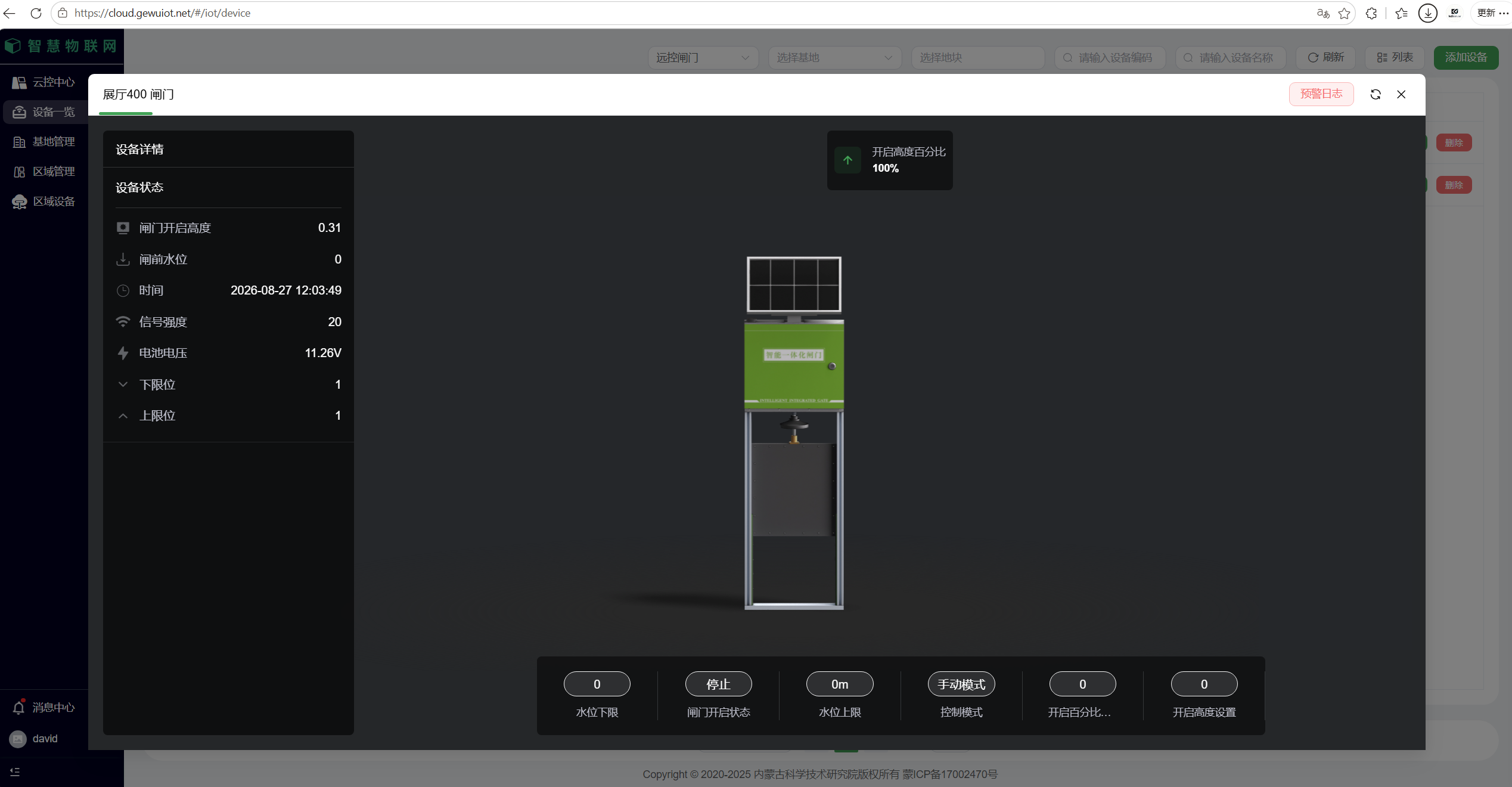
Real‑time display of full‑dimensional parameters: equipment status, gate opening height, water‑level thresholds, battery voltage, signal strength, etc. Automatically stores historical data and operation logs. Batch‑select multiple pieces of equipment for remote management. Freely toggle manual / automatic control modes and customize water‑level‑linkage rules. Supports data export and remote equipment‑status diagnosis.

6.2 Local Operation
Physical‑button Control
Press and hold UP button for 1 s to open gate; press and hold STOP button for 1 s to halt movement; press and hold DOWN button for 1 s to close gate. Cut off power supply via power key for emergency stop.
Touch‑screen Operation
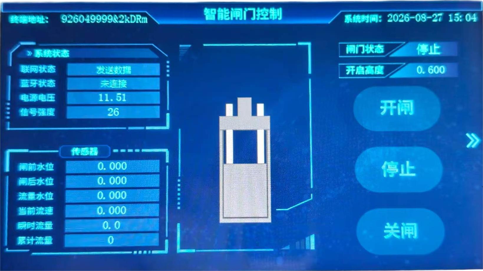
Wake‑up touch‑screen by pressing any button (STOP button recommended). Tap UP / STOP / DOWN icons on screen to control gate movement. Users may also enter parameter‑configuration page to set automatic upstream‑ / downstream‑water‑level control.
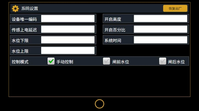
Small‑screen unit: functions identical to full‑size touch‑screen.
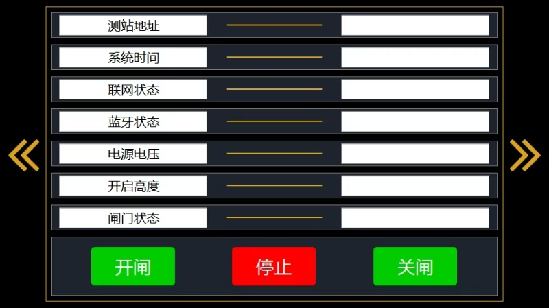
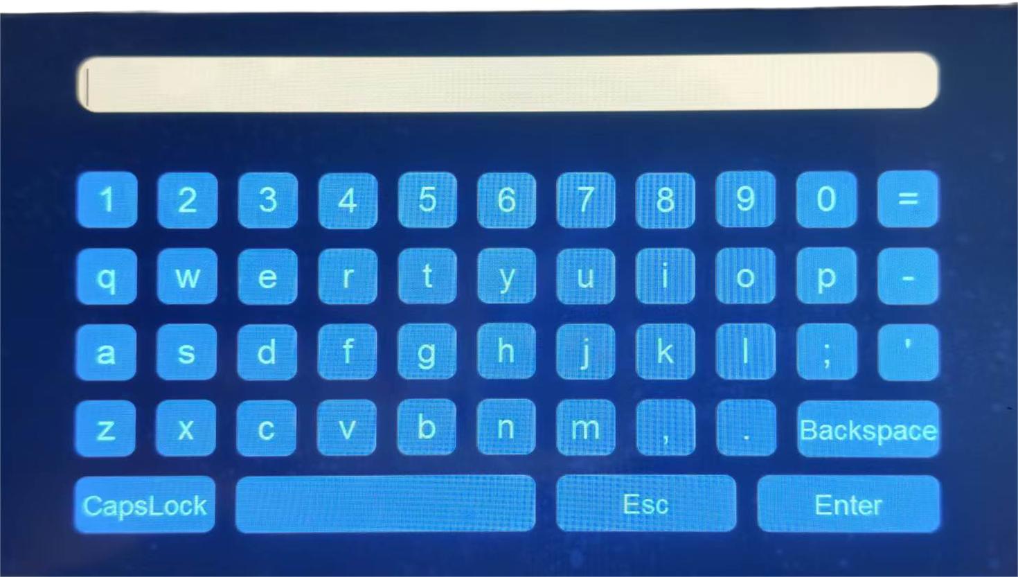
Tap right‑arrow icon to enter login page.
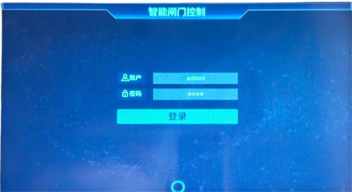
Please contact our company to obtain login password.
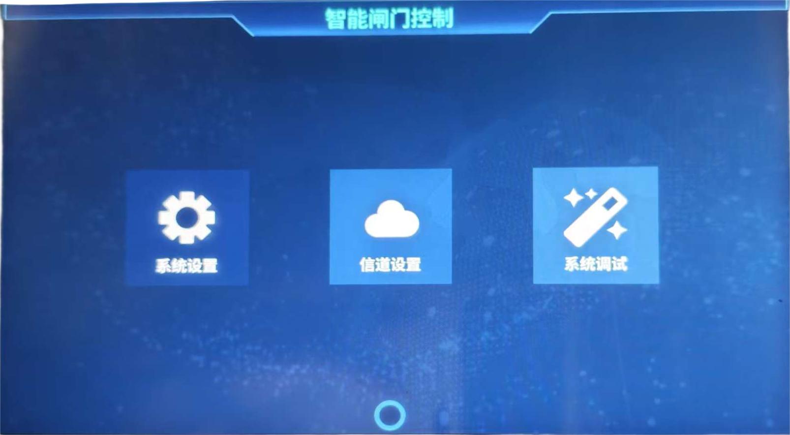
Select menu items after login; circular icon at bottom is return‑to‑previous‑page button.
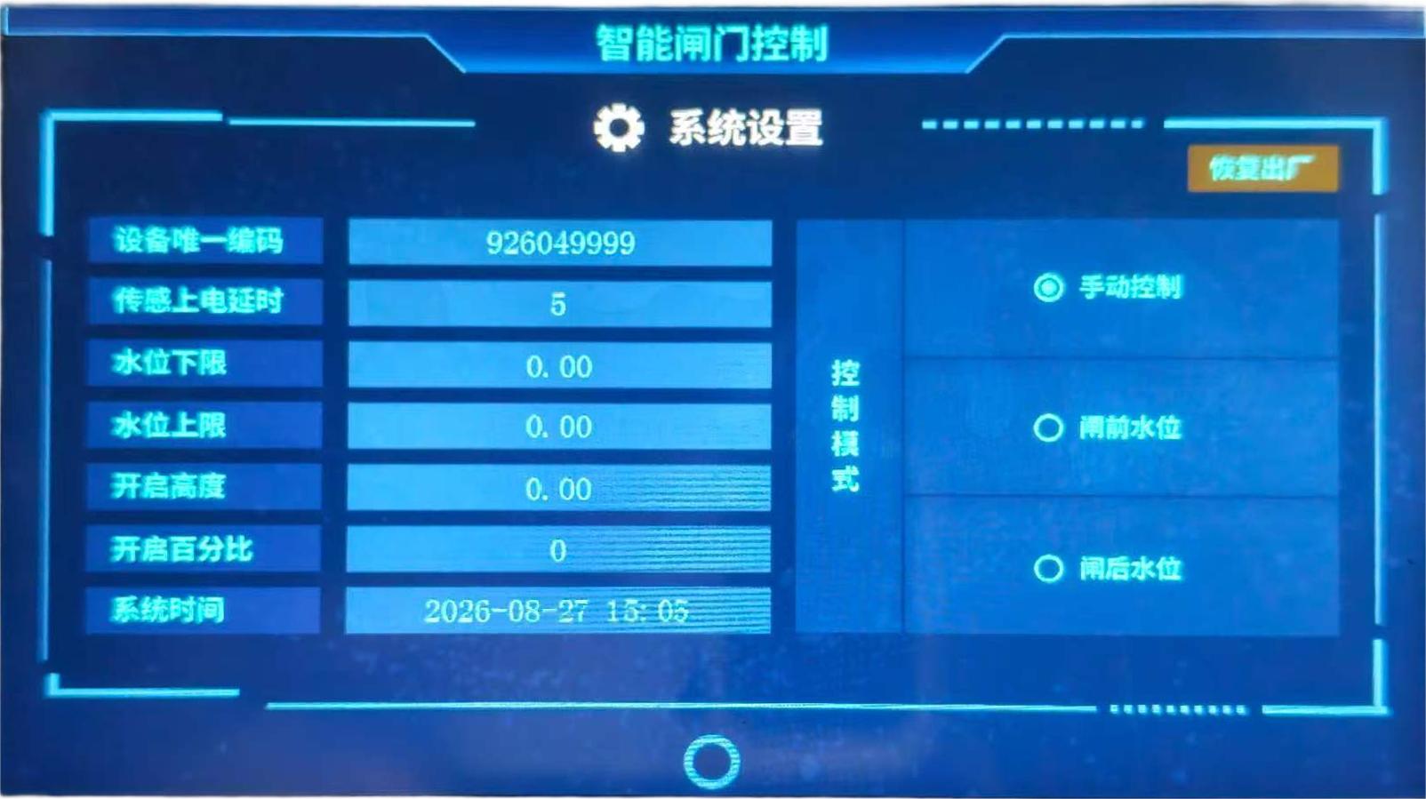
System Settings: Configure opening‑percentage, water‑level upper/lower‑limits, control‑mode and other parameters.
Small‑screen unit: functions identical to full‑size touch‑screen.
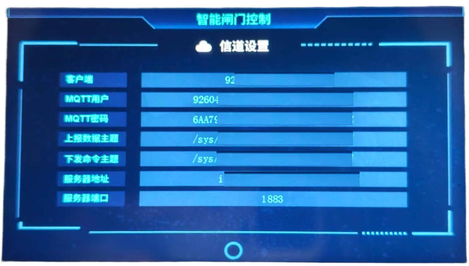
Channel‑communication parameters are factory‑preconfigured. Do NOT modify unless absolutely necessary.
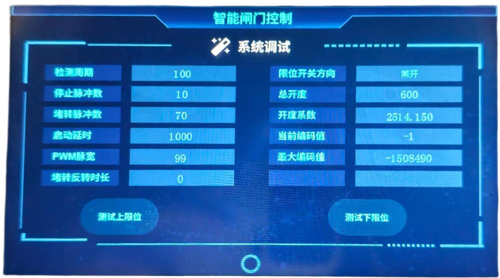
System‑commissioning parameters are factory‑preconfigured. Do NOT modify unless absolutely necessary. Contact our technical‑support team for parameter changes.
Bluetooth Control
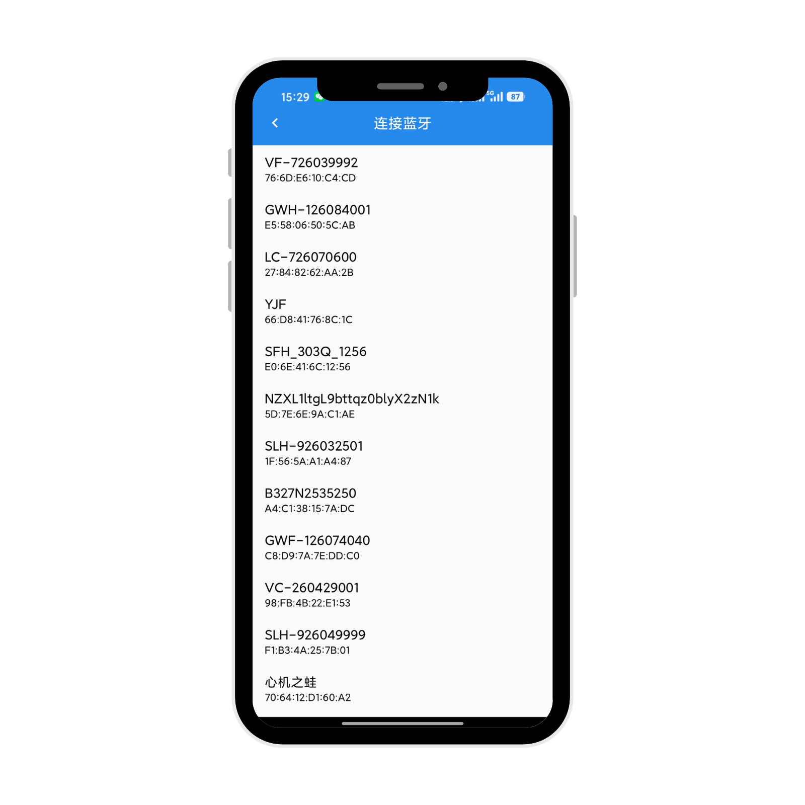
Launch mobile APP, select Bluetooth device matching station ID and tap to establish connection.
Select Operation‑parameters menu.
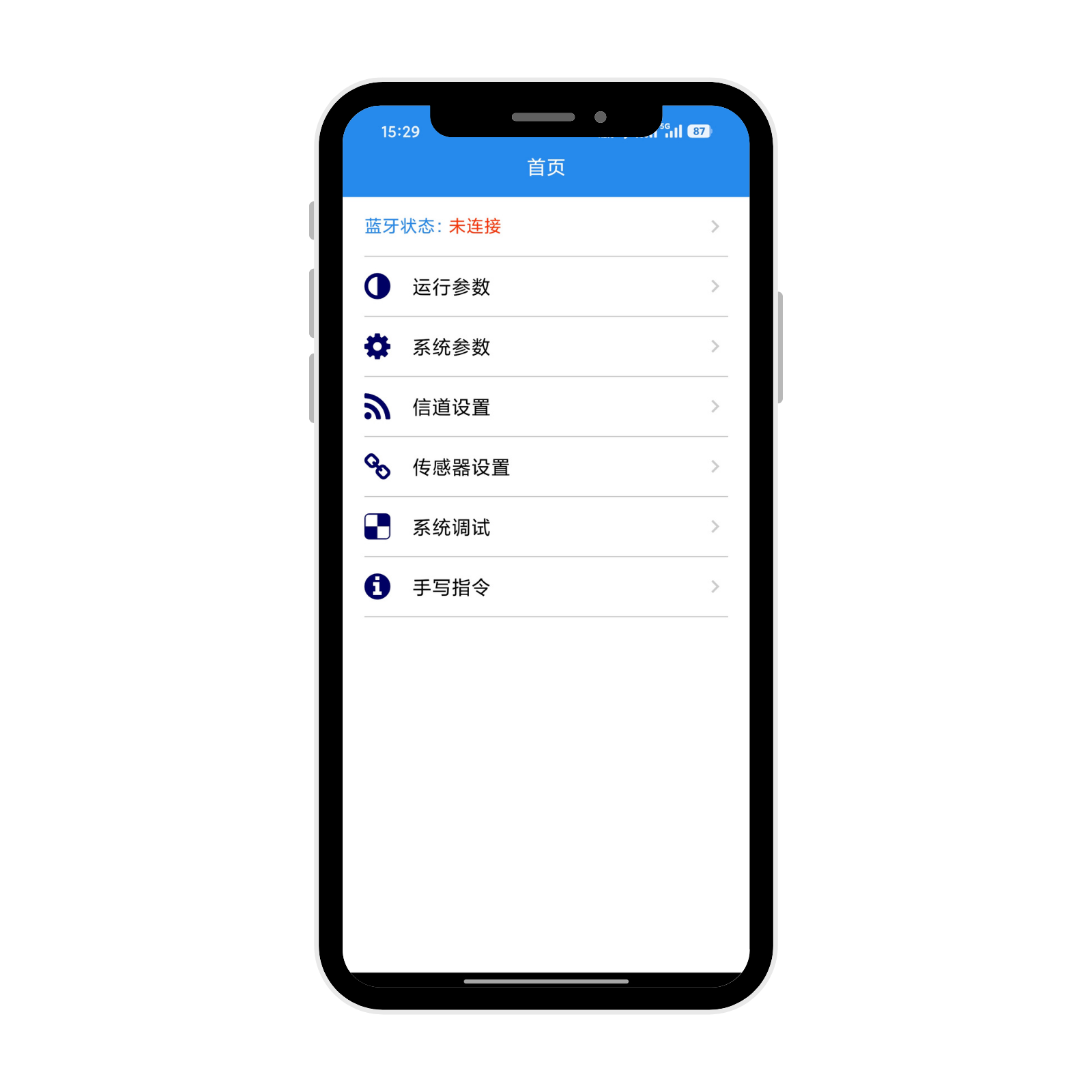
Real‑time gate‑status data will be displayed. Tap UP / STOP / DOWN icons to control gate movement.
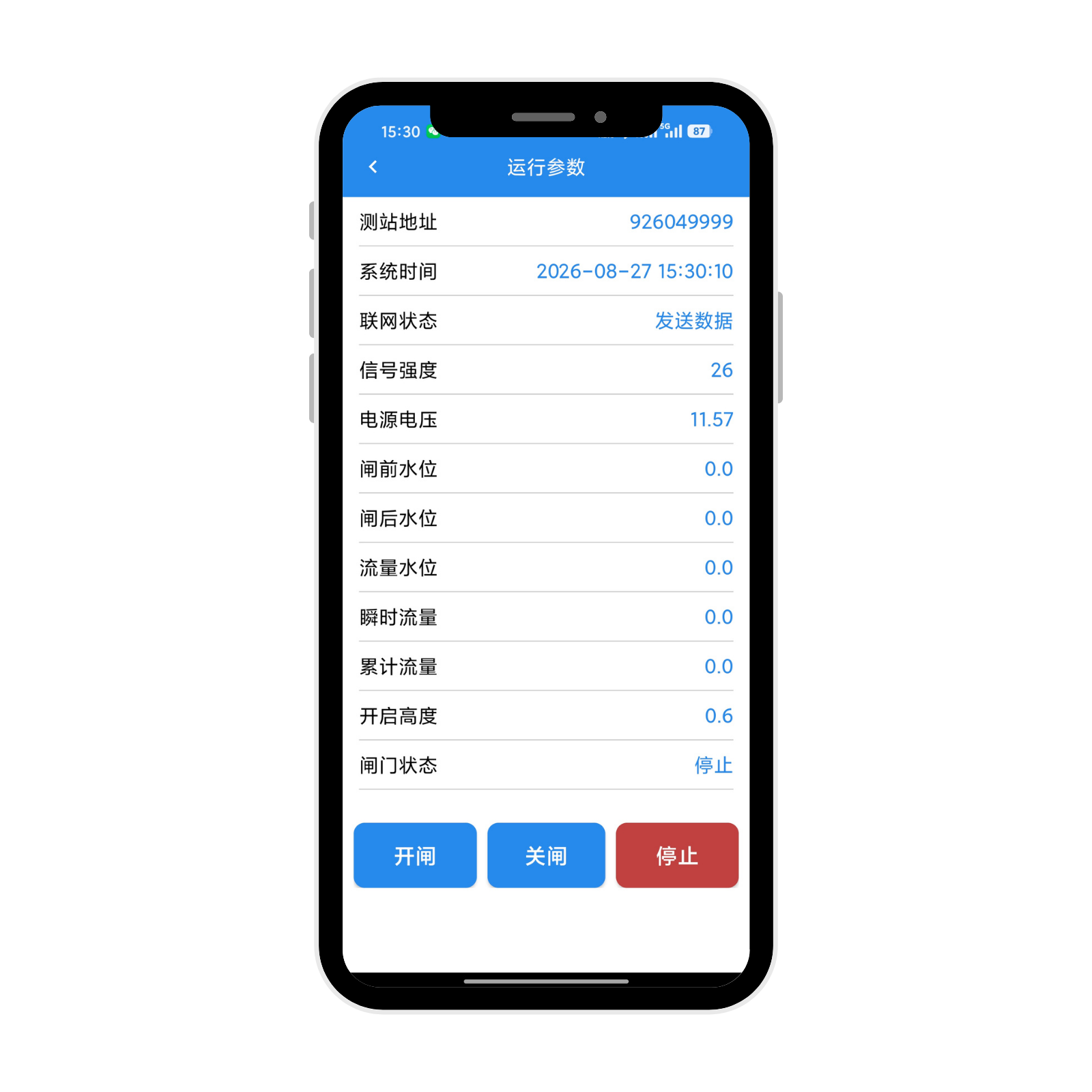
Users may also configure automatic‑control‑mode and water‑level upper/lower‑limits under System‑parameters menu for automatic‑control operation.
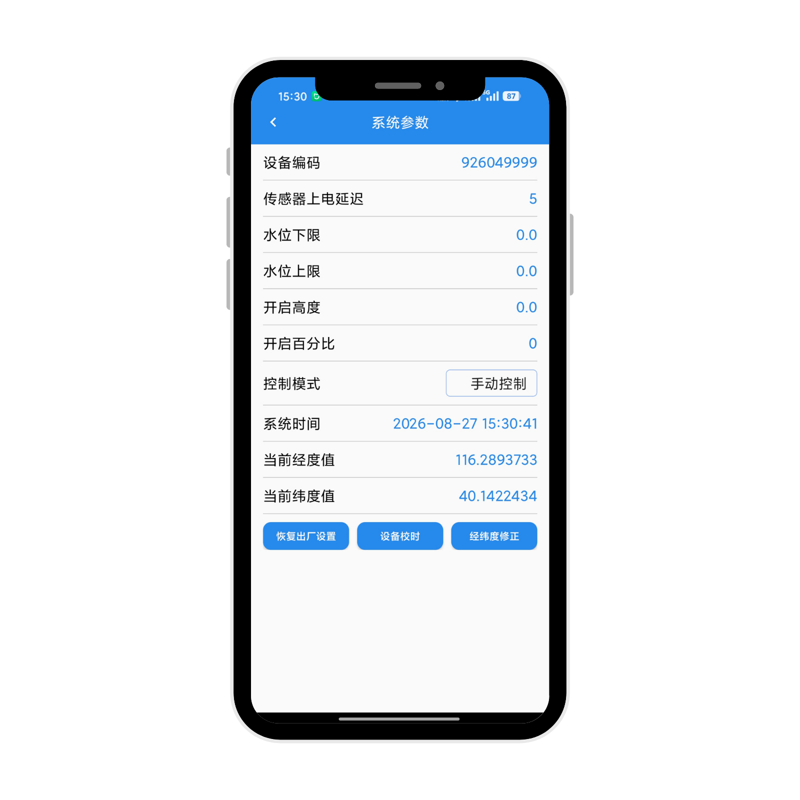
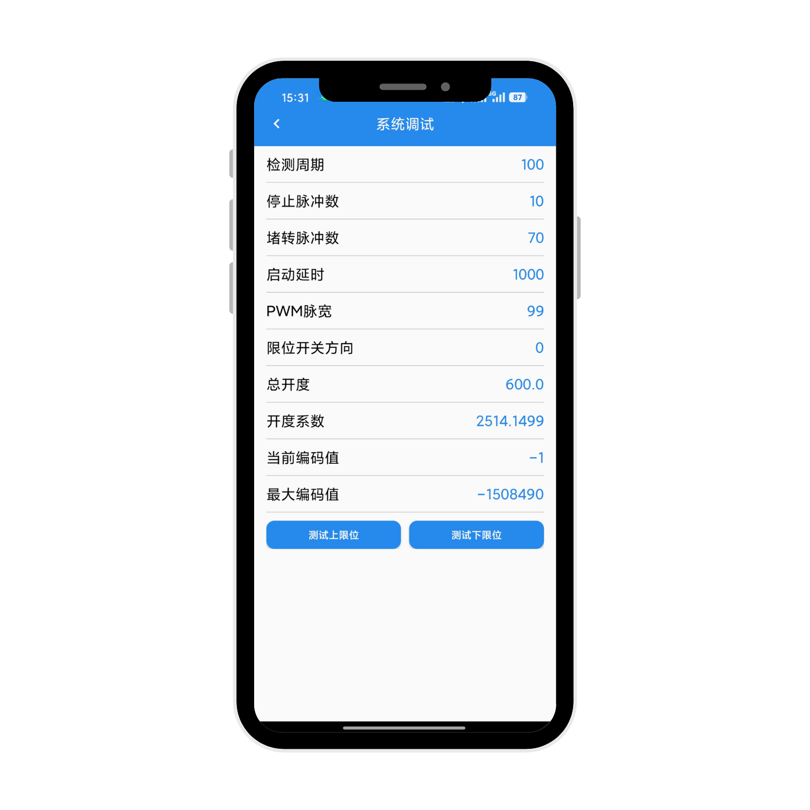
Enter System‑commissioning menu to configure automatic‑control‑mode and water‑level thresholds.
System‑commissioning parameters are factory‑preconfigured. Do NOT modify unless absolutely necessary. Contact our technical‑support team for parameter changes.
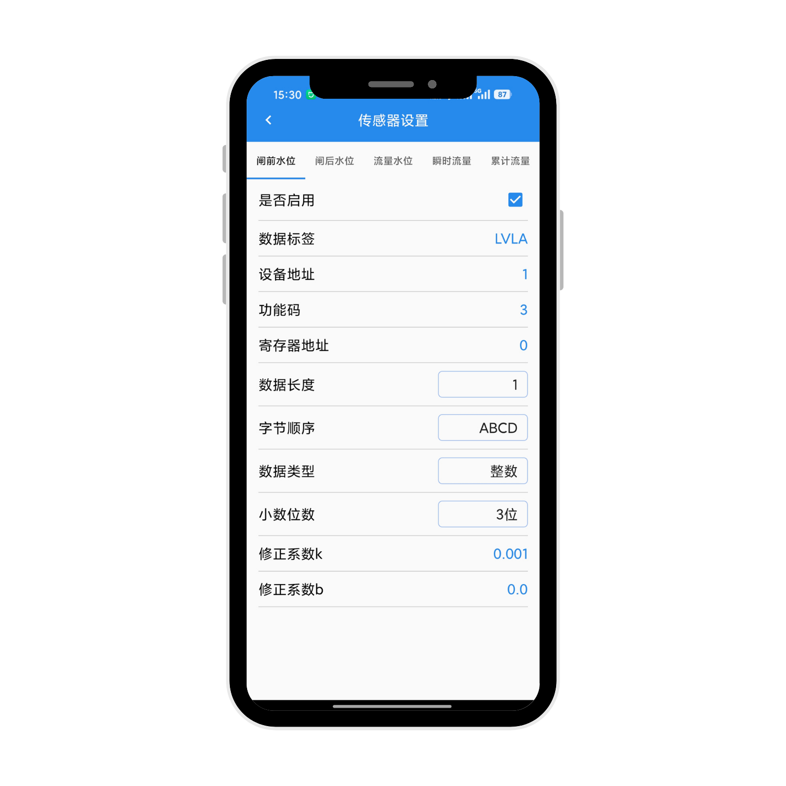
Enter Sensor‑parameter menu to configure sensor‑acquisition tasks for sensor‑data access.
Official website: www.gewuiot.com Tel: +86‑15830040128